


3. SPECIFICATION
Model No: ................................................ SUPERMIG275.V2
Welding Current: .......................................................40-270A
Wire Capacity:............................................................. 5-15kg
Duty Cycle: ........100% @ 112A, 60% @ 146A, 20% @ 255A
Cooling System: .....................................................Forced Air
Spot Welding Timer: ......................................................... Yes
Gas Type:.................................. CO2, Argon, CO2/Argon Mix
Torch: ............................ 3m Euro Non-Live - BINZEL® MB24
Supply: ....................................................................230V-55A
Absorbed Power: ....................................................... 12.6kW
Case Size: ......................................................... Extra-Large
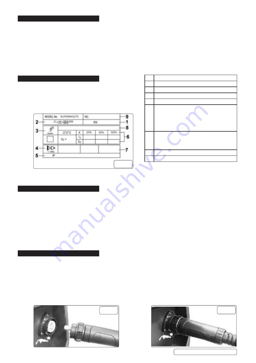
4. RATING PLATE
Detailed technical data relative to the performance of the machine
is located on the back panel.
NOTE:
The ratings plate detailed below (fig.1) is an example only
intended to assist with the explanations of the symbols. To determine
the correct technical values of the machine refer to the data plate on
your machine and the specification table above.
5. CONTENTS
5.1.
UNPACKING
5.1.1.
Unpack the product and check contents. Take care to ensure safety when removing product from it’s packaging. Seek assistance
from another person as the welding unit is heavy. Should there be any damaged or missing parts contact your supplier
immediately.
5.2.
CONTENTS
Main Welding Unit.
Wire Feed Roller 0.8mm/1.0mm x 1.
Torch & Cable with Euro connector.
Welding Tip 0.8 and gas cap.
Earth Clamp Cable.
Industrial Gas Regulator.
Gas Bottle Retaining Chain.
6. ASSEMBLY
NOTE:
The welding set is supplied with the wheels and handles fully assembled.
6.1.
CONNECT WELDING SET TO THE MAINS POWER SUPPLY
6.1.1.
Before making any electrical connections, ensure that the mains voltage and frequency of the supply matches the electrical
specification of the welding set as stated on the welding set’s rating plate (fig.1).
6.1.2.
The welding set must only be connected to a 30 Amp fused power supply as described in section 1.
6.1.3.
Refer to the section on electrical safety at the start of these instructions for information on the correct connection of the mains power
plug.
6.2.
CONNECT TORCH “Euro Connection”
6.2.1.
The welding set is fitted with a “Euro Connection” quick release torch. Line up the pins in the torch connector with the appropriate
holes in the socket on the front panel connector (fig.2), push in, engage and tighten the locking nut (fig.3).
Supermig275.V2 Issue 1 10/01/22
Original Language Version
© Jack Sealey Limited
1
Relevant standard
2
Single phase transformer - rectifier
3
Welding with a continuous flow of welding wire
4
Single-phase AC supply
5
Case protection class
6
Output
U0: Rated maximum and minimum no load voltage
I2,U2: Current and corresponding voltage
X: Welding ratio based on a 10 minute cycle
20% = 2 minutes welding 8 minutes rest
100% = continuous welding
7
Mains supply
U1: Rated suply voltage and frequency
I1 max: Maximum current
I1eff: Maximum effective current
8
Welding current range
9
Serial number
fig.1
fig.2
fig.3


