background image

6.3. 


CONNECTING THE WELDING CURRENT RETURN CABLE
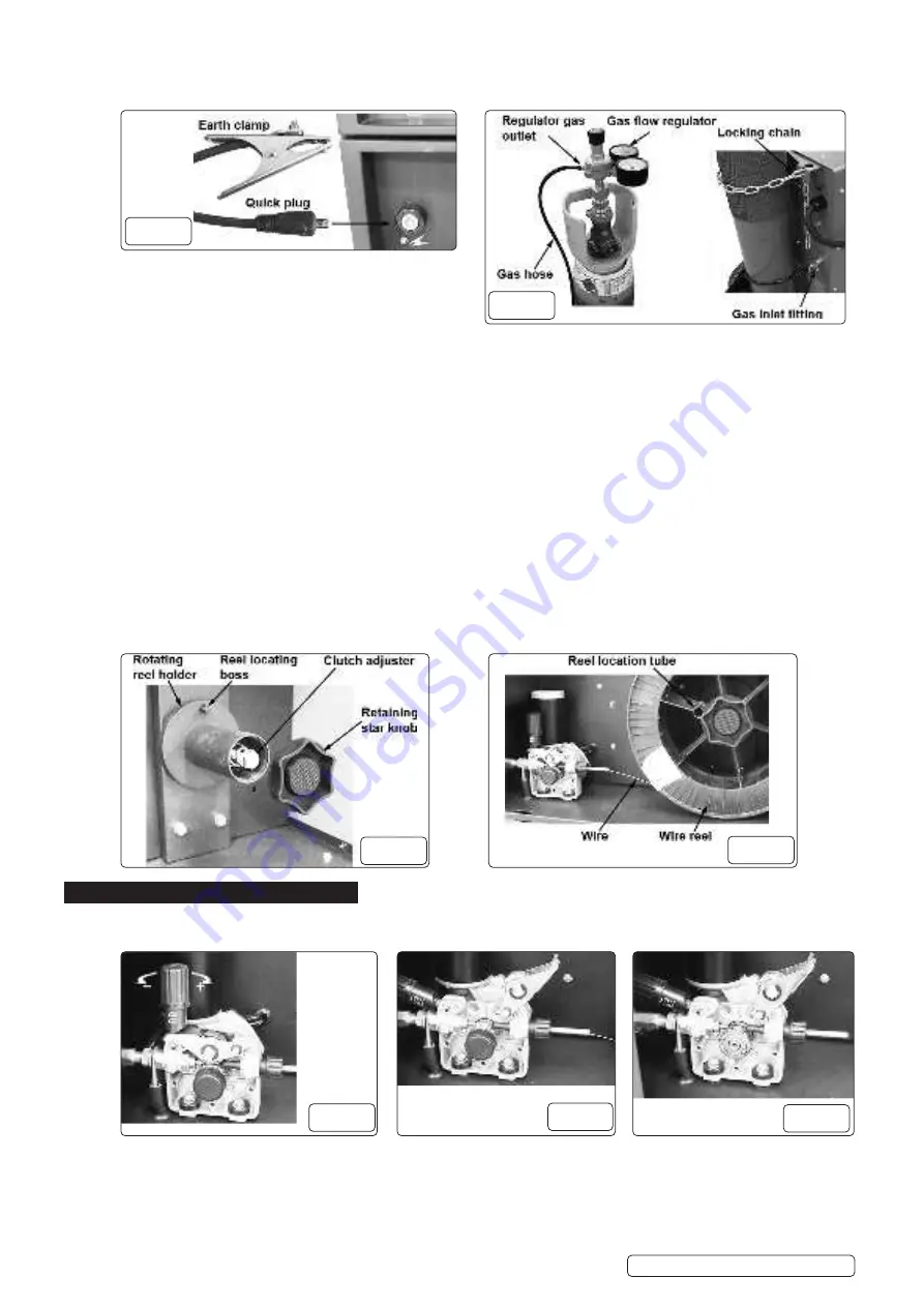
6.3.1. 


Firmly attach the earthing clamp 

(fig.4)


to the workpiece, or to a metal support structure, as close as possible to the joint being made.

6.3.2. 


Insert the quick connector 

(fig.4) 

into the earth clamp socket located on the lower front panel.

6.4.    

MOUNT THE GAS CYLINDER

6.4.1.   

Stand the gas cylinder on the platform at the rear of the welding set and secure with locking chain (fig.5).


‰


WARNING!

 The platform is designed to support bottles up to a maximum weight of 20kg.

6.5. 


FITTING THE FLOW REGULATOR

6.5.1. 


If using CO2 gas, screw the flow regulator directly into the cylinder, and tighten with correct size spanner (fig.5).

6.5.2. 


If using argon or argon mixture gas, the supplied “bull nose adaptor” should be fitted to the cylinder and be tighten with correct size    


spanner, then screw the flow regulator into the “bull nose adaptor”, and tighten with correct size spanner (fig.5).

6.5.3. 


Remove the flow regulator and store in a dry childproof location if the welding set is to be stored for any length of time.


NOTE:

 The supplied flow regulator may differ from that illustrated.

6.6. 


ATTACH THE GAS HOSE

6.6.1. 


Push the free end of the gas hose fully onto the flow regulator gas outlet connection (fig.5).

6.6.2. 


Screw the brass fitting onto the gas inlet fitting on the rear of the welding set and tighten with correct size spanner (fig.5).

6.7. 


FITTING A REEL OF WIRE


‰


WARNING!

 Ensure the welding set is unplugged from the mains power.


NOTE:

 The wire feed reel holder will accept reels of up to 15kg.

6.7.1. 


Open the wire feed compartment and unscrew and remove the retaining star knob (fig.6) and place to one side.

6.7.2. 


Slide the wire reel onto the reel holder (fig.6) and locate the reel location tube on the wire reel with the reel location boss (fig.7) on the  


reel holder.

6.7.3. 


Reattach the retaining star knob and fully tighten (fig.7).

6.7.4. 


Ensure that the wire is spooling off from the bottom of the wire reel in the direction of the wire drive unit (fig.7).

7.  FEED WIRE THROUGH TORCH


‰


WARNING!

 Ensure that the wire feed roller, the wire guide hose and the contact tip of the torch correspond to the diameter and    

  type of wire to be used and are fitted correctly.

7.1. 


To access the drive mechanism pull the pressure adjustment knob to the left and allow it to rotate downwards (fig.8). The pressure  


roller housing will then spring open, rotating to the right (fig.9).

7.1.1. 


Ensure that the required feed groove (Ø0.8mm and Ø1.0mm wire) is in line with the wire path. See section 7.4 on how to reverse or   


change the roller.

7.1.2. 


Release the wire from the reel and trim off any bent portion and remove any burrs.

Supermig275.V2  Issue 1 10/01/22

Original Language Version

© Jack Sealey Limited

   fig.4

   fig.5

   fig.6

   fig.7

   fig.8

   fig.9

 fig.10

Summary of Contents for SUPERMIG275.V2

Page 1: ...nd use a Portable Appliance Tester PAT 1 1 5 Ensure that cables are always protected against short circuit and overload 1 1 6 Regularly inspect power supply leads plugs and all electrical connections for wear and damage Inspect power connections to ensure that none is loose IMPORTANT Ensure the voltage marked on the product is the same as the electrical power supply to be used and check that plugs...

Page 2: ... live metal parts of the torch or electrode while the welding set is switched on 8 DO NOT pull the welding set by the cable or the torch Protect cables from sharp or abrasive items DO NOT bend strain or stand on cables or leads 9 Protect from heat Long lengths of slack must be gathered and neatly coiled DO NOT place cables where they endanger others 8 DO NOT touch the torch or workpiece immediatel...

Page 3: ...andles fully assembled 6 1 CONNECT WELDING SET TO THE MAINS POWER SUPPLY 6 1 1 Before making any electrical connections ensure that the mains voltage and frequency of the supply matches the electrical specification of the welding set as stated on the welding set s rating plate fig 1 6 1 2 The welding set must only be connected to a 30 Amp fused power supply as described in section 1 6 1 3 Refer to...

Page 4: ...he gas inlet fitting on the rear of the welding set and tighten with correct size spanner fig 5 6 7 FITTING A REEL OF WIRE WARNING Ensure the welding set is unplugged from the mains power NOTE The wire feed reel holder will accept reels of up to 15kg 6 7 1 Open the wire feed compartment and unscrew and remove the retaining star knob fig 6 and place to one side 6 7 2 Slide the wire reel onto the re...

Page 5: ... your gloved fingers If the top feed rollers skid the tension is correct Use as low a tension as possible too high a tension will deform wire and result in a blown fuse on the printed circuit board Adjust tension by turning the pressure knob fig 8 7 3 CLUTCH ADJUSTMENT NOTE It is essential that the clutch is adjusted correctly 7 3 1 Once the wire is fed through the torch switch on the welding set ...

Page 6: ...ng quality Clean the rollers weekly removing all dust deposits 9 2 TORCH 9 2 1 Protect the torch cable assembly from mechanical wear Clean the liner from the machine forwards with compressed air Replace the liner if it becomes clogged 9 3 FEED ROLLER REPLACEMENT 9 3 1 See section 7 4 9 4 CONTACT TIP 9 4 1 The contact tip is a consumable item and must be replaced when the hole becomes enlarged or o...

Page 7: ...Pressure roller tension improper Clean the liner from the machine forward Use compressed air Replace gas cup nozzle and or tip Clean or replace gas cup nozzle Clean feed roller Replace feed roller Adjust tension 7 Unstable arc Incorrect settings Impurities in weld area Worn or defective gas cup nozzle Check settings Clean and or grind workpiece Replace gas cup nozzle 8 Porous weld No gas Gas cup c...

Reviews: