


WARNING!
Prevent the wire from uncoiling by keeping the wire under tension at all times.
7.1.3.
Straighten 50-100mm of wire and gently push it through the flexible metal sheathed cable (fig.7) over the feed roller groove and then
into the torch cable liner.
7.1.4.
Push down the pressure roller onto the wire feed roller and hold it down then rotate the pressure knob upwards and onto the housing
until it snaps into position (fig.8).
7.1.5.
Rotate the tension knob to a medium pressure setting between 2 and 3.
NOTE:
Turning the knob clockwise increases the pressure and turning anti-clockwise decreases the pressure (fig.8).
7.1.6.
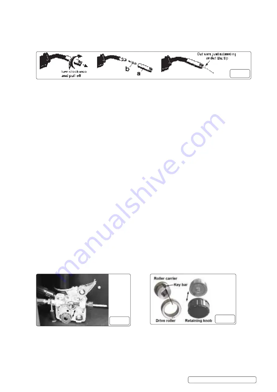
Remove the gas cup by turning clockwise and pull it off the end of the torch (fig.11 a).
WARNING! DO NOT
turn the gas cup anti-clockwise. This will damage the internal spring.
7.1.7.
Unscrew the copper contact tip (fig.11 b).
7.1.8.
Check that the welding set is switched off at position “0” and that the earth clamp is isolated away from the torch tip.
7.1.9.
Connect the welding set to the mains power supply and set the voltage switch to “1”.
7.1.10.
Set the wire speed control knob to position 5 or 6. Keep the torch cable as straight as possible and press the torch switch and the
wire will feed through the torch.
7.1.11.
When the wire has fully fed through, switch the welding set off and unplug from the mains.
7.1.12.
Slide the contact tip over the wire and screw back into position.
7.1.13.
Reattach the gas cup.
WARNING! DO NOT
turn the gas cup anti-clockwise. This will damage the internal spring.
7.1.14.
Cut the wire so that it is just protruding from the gas cup (fig.11).
7.2.
SETTING THE WIRE TENSION
7.2.1.
Adjust the wire tension by turning the wire tension knob (fig.8). Turn clockwise to increase the tension and anti-clockwise to decrease
the tension.
IMPORTANT:
Too little or too much tension will cause problematic wire feed and poor weld quality.
7.2.2.
Tension between rollers is checked by slowing down the wire between your gloved fingers. If the top feed rollers skid the tension is
correct. Use as low a tension as possible; too high a tension will deform wire and result in a blown fuse on the printed circuit board.
Adjust tension by turning the pressure knob (fig.8).
7.3.
CLUTCH ADJUSTMENT
NOTE:
It is essential that the clutch is adjusted correctly.
7.3.1.
Once the wire is fed through the torch, switch on the welding set and set the wire speed to maximum.
7.3.2.
Depress the torch switch and release quickly. If the spool overruns this indicates that the clutch is too loose.
7.3.3.
Tighten the clutch nut located in the centre of the wire spool holder with a correct sized spanner (fig.6).
7.3.4.
Re-test the clutch adjustment, as described above, until the wire stops overrunning.
8
DO NOT
over tighten the clutch as this will cause wire speed problems and strain the motor.
7.4.
TURNING/CHANGING THE DRIVE ROLLER
NOTE:
Ensure that the contact tip, the groove size on the drive wheel and torch liner correspond to the wire diameter being used. Failure
to do this could cause the wire to slip and/or bind.
7.4.1.
Open the wire feed mechanism. See section 7.1.
7.4.2.
Unscrew and remove the black feed roller retaining knob (fig.10), and put to one side.
7.4.3.
The roller carrier (fig.13) is keyed to the main drive shaft and the drive roller (fig.13) is keyed to the carrier.
7.4.4.
With care slide the slide the drive roller off the carrier. Ensure the key bars remain in place (fig.12).
NOTE:
The size of each wire feed groove is marked on the edge of the roller on the same side as the groove.
7.4.5.
Reverse or replace the drive roller as required. The required groove should be positioned furthest away from you and be in line with the
drive path.
7.4.6.
Replace the drive roller. Ensure that the keyway’s are aligned.
7.4.7.
Reattach the black feed roller retaining knob and tighten.
7.4.8.
Close the wire feed mechanism. See section 7.1.4
7.5.
WIRE FEED CONTROL
7.5.1.
Select the desired wire feed with the ‘Wire Feed Control’ control located on the front panel of the welding set (fig.14).
Supermig275.V2 Issue 1 10/01/22
Original Language Version
© Jack Sealey Limited
fig.11
fig.12
fig.13


