background image

8.  CONTROLS

8.1. 


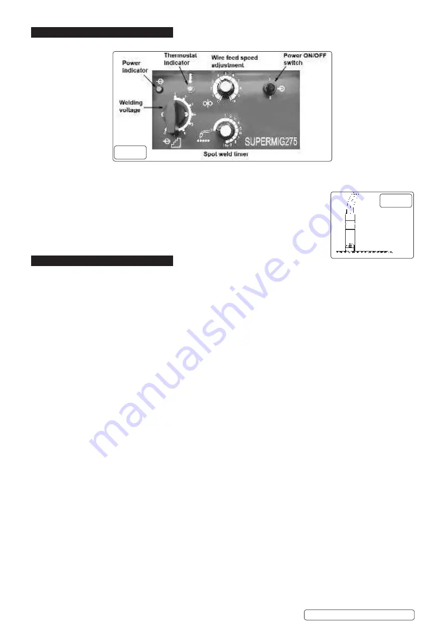
Fig 14 illustrates the main panel control for the Supermig 275.

8.2. 


SYSTEM PROTECTION


A thermostat is built into the system to protect against overheating. The indicator light comes on when overheating occurs and cuts  


  off the power supply. It will reset automatically within a few minutes, after cooling down.

8.3. 


SPOT WELDING

8.3.1. 


Switch the welding set to the SPOT mode position.

8.3.2. 


Remove the gas cup, see section 7.1.6 and replace it with the spot welding cap (fig.15).

8.3.3. 


Set the voltage to highest setting (fig.14).

8.3.4. 


Set the wire speed at almost maximum speed (fig.14).

8.3.5. 


Turn ON the Spot Weld Timer to the desired time to suit thickness of plate being spot welded (fig.14).

8.3.6. 


Press the torch button until the spot welding timer cuts in to stop the welding.

8.3.7. 


Repeat as required.

9.  MAINTENANCE

9.1. 


WIRE FEED UNIT

9.1.1. 


Check the wire feed unit at regular intervals. The feed roller wire guide plays an important part in obtaining consistent welding results.  


Poor wire feed affects welding quality. Clean the rollers weekly removing all dust deposits.

9.2. 


TORCH

9.2.1. 


Protect the torch cable assembly from mechanical wear. Clean the liner from the machine forwards with compressed air. Replace the  


liner if it becomes clogged.

9.3. 


FEED ROLLER REPLACEMENT

9.3.1. 


See section 7.4.

9.4. 


CONTACT TIP

9.4.1. 


The contact tip is a consumable item and must be replaced when the hole becomes enlarged or oval. The contact tip must be kept    


free from spatter to ensure an unimpeded flow of gas.

9.5. 


GAS CUP

9.5.1. 


The gas cup must also be kept clean and free from spatter. Build up of spatter inside the gas cup can cause a short circuit at the  


contact tip which will result in either the fuse blowing on the printed circuit card, or expensive machine repairs.


  To keep the contact tip free from spatter, we recommend the use of Sealey anti-spatter spray (MIG/722307) available from your  


  Sealey stockist.

9.6. 


REPLACING THE LINER

9.6.1. 


Wind the wire back onto the spool and secure.

9.6.2. 


Unscrew the torch from the welding set and undo the brass nut.

9.6.3. 


The liner should now be visible.

9.6.4. 


Pull the line out and replace with a new one.

 fig.14

Supermig275.V2  Issue 1 10/01/22

Original Language Version

© Jack Sealey Limited

 fig.15

Summary of Contents for SUPERMIG275.V2

Page 1: ...nd use a Portable Appliance Tester PAT 1 1 5 Ensure that cables are always protected against short circuit and overload 1 1 6 Regularly inspect power supply leads plugs and all electrical connections for wear and damage Inspect power connections to ensure that none is loose IMPORTANT Ensure the voltage marked on the product is the same as the electrical power supply to be used and check that plugs...

Page 2: ... live metal parts of the torch or electrode while the welding set is switched on 8 DO NOT pull the welding set by the cable or the torch Protect cables from sharp or abrasive items DO NOT bend strain or stand on cables or leads 9 Protect from heat Long lengths of slack must be gathered and neatly coiled DO NOT place cables where they endanger others 8 DO NOT touch the torch or workpiece immediatel...

Page 3: ...andles fully assembled 6 1 CONNECT WELDING SET TO THE MAINS POWER SUPPLY 6 1 1 Before making any electrical connections ensure that the mains voltage and frequency of the supply matches the electrical specification of the welding set as stated on the welding set s rating plate fig 1 6 1 2 The welding set must only be connected to a 30 Amp fused power supply as described in section 1 6 1 3 Refer to...

Page 4: ...he gas inlet fitting on the rear of the welding set and tighten with correct size spanner fig 5 6 7 FITTING A REEL OF WIRE WARNING Ensure the welding set is unplugged from the mains power NOTE The wire feed reel holder will accept reels of up to 15kg 6 7 1 Open the wire feed compartment and unscrew and remove the retaining star knob fig 6 and place to one side 6 7 2 Slide the wire reel onto the re...

Page 5: ... your gloved fingers If the top feed rollers skid the tension is correct Use as low a tension as possible too high a tension will deform wire and result in a blown fuse on the printed circuit board Adjust tension by turning the pressure knob fig 8 7 3 CLUTCH ADJUSTMENT NOTE It is essential that the clutch is adjusted correctly 7 3 1 Once the wire is fed through the torch switch on the welding set ...

Page 6: ...ng quality Clean the rollers weekly removing all dust deposits 9 2 TORCH 9 2 1 Protect the torch cable assembly from mechanical wear Clean the liner from the machine forwards with compressed air Replace the liner if it becomes clogged 9 3 FEED ROLLER REPLACEMENT 9 3 1 See section 7 4 9 4 CONTACT TIP 9 4 1 The contact tip is a consumable item and must be replaced when the hole becomes enlarged or o...

Page 7: ...Pressure roller tension improper Clean the liner from the machine forward Use compressed air Replace gas cup nozzle and or tip Clean or replace gas cup nozzle Clean feed roller Replace feed roller Adjust tension 7 Unstable arc Incorrect settings Impurities in weld area Worn or defective gas cup nozzle Check settings Clean and or grind workpiece Replace gas cup nozzle 8 Porous weld No gas Gas cup c...

Reviews: