4. PREPARING INVERTER FOR USE
3. CONTROLS
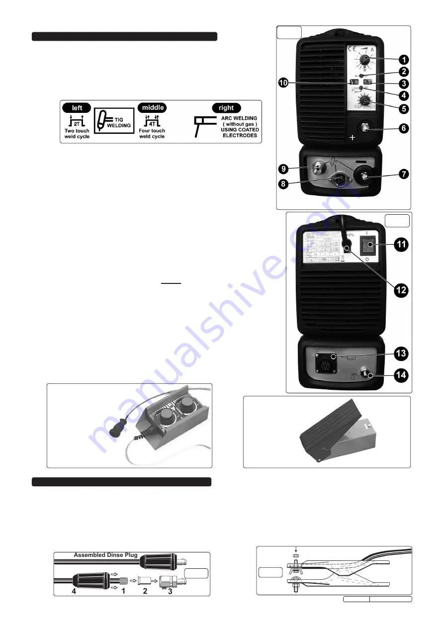
3.1 FRONT PANEL LAYOUT (refer to Figure 2).
1.
WELDING CURRENT CONTROL.
Potentiometer has scale graduated in Amps. Also allows adjustment during welding.
2.
TIG START MODE SWITCH.
With the switch to the left
‘HF’
(high frequency) start mode is
selected. With the switch to the right
‘LIFT’
start mode is selected.
3.
GREEN LED.
Shows that the machine is connected to the mains and ready for operation.
4.
WELDING MODE SWITCH
(three positions).
Selects the type of welding and the torch push button functions in TIG welding mode.
5.
DUAL FUNCTION CONTROL.
During TIG welding this potentiometer is used to adjust
‘current slope down time’
which occurs after the torch is turned off. During ARC welding
(without gas) using coated electrodes the potentiometer is used to adjust
‘arc force’
.
6.
DINSE SOCKET
(positive
+
).
For the connection of a welding cable Dinse plug.
7.
DINSE SOCKET
(negative
-
).
For the connection of a welding cable Dinse plug.
8.
CONNECTOR SOCKET.
For the connection of torch push button cable.
9. GAS PIPE FITTING.
For the connection of the TIG torch gas tube.
10.
FAULT INDICATOR
(Yellow LED normally off). When ON the welding current is shut off
due to one of the following faults:
Thermal protection.
The temperature inside the machine is too high. The machine is ON but
will not deliver current until it cools to normal temperature. Once this happens it will re-start
automatically.
Mains over/under voltage protection.
When the mains voltage is either too high or too low
the machine is blocked.
Short circuit protection.
In case there is a short-circuit lasting more than 1.5 seconds (e.g.
electrode striking), the machine stops. The welder will restart automatically.
3.2 REAR PANEL LAYOUT (refer to Figure 3).
11.
MAIN ON/OFF SWITCH
(Illuminated).
12.
MAINS CABLE.
13.
REMOTE CONTROL CONNECTOR.
See
optional
remote controls shown below.
Pedal Remote control (Model No. INV/TIG/5)
- Allows hands free adjustment of the welding
current and can also be used to stop and start the weld without using the torch button.
Remote Control with two potentiometers (Model No. INV/TIG/7)
- The potentiometer
labelled ‘Power’ allows continuous adjustment of the welding current. The other potentiometer
allows adjustment of the ‘down slope time’ in TIG mode and adjustment of ‘arc force’ during
ordinary arc welding without gas.
14.
GAS INLET FITTING.
For connecting gas cylinder to the welder using clear tubing provided.
Fig 4
Fig 5
(Model No. INV/TIG/5)
Pedal Remote control
(Model No. INV/TIG/7)
Remote Control with
two potentiometers
4.1
CONNECTION TO THE MAINS.
The unit is fitted with a 13Amp plug and is designed to operate in both welding modes on a 13Amp supply. If
however the unit is used consistently at high output, connection to a 30Amp supply may be considered. Seek the advice of a qualified
electrician on connection to a suitable supply.
4.2
WELDING CABLE CONNECTIONS.
The torch cable is supplied ready assembled but it may be necessary for you to assemble the work clamp cable.
Attach the work clamp to one end of the cable as shown in fig.5. To connect the Dinse Plug as shown in fig.4 first thread the cable through the outer
cover of the plug (see fig.4 - 4). Now remove 20mm of insulation sheath from the end of the cable and fold back the copper wire all around the outside of
the sheath (1). Push the cable end into the copper sleeve (2) so that the folded back wire makes good contact with the inside of the sleeve. Push the
copper sleeve into the brass plug body (3) and tighten the large grub screw until the cable is firmly held. Now slide the outer plug cover up the cable and
press the brass body into it as shown in fig.4.
Original Language Version
TIG160HF Issue: 1 - 31/10/11
fig 3
fig 2


