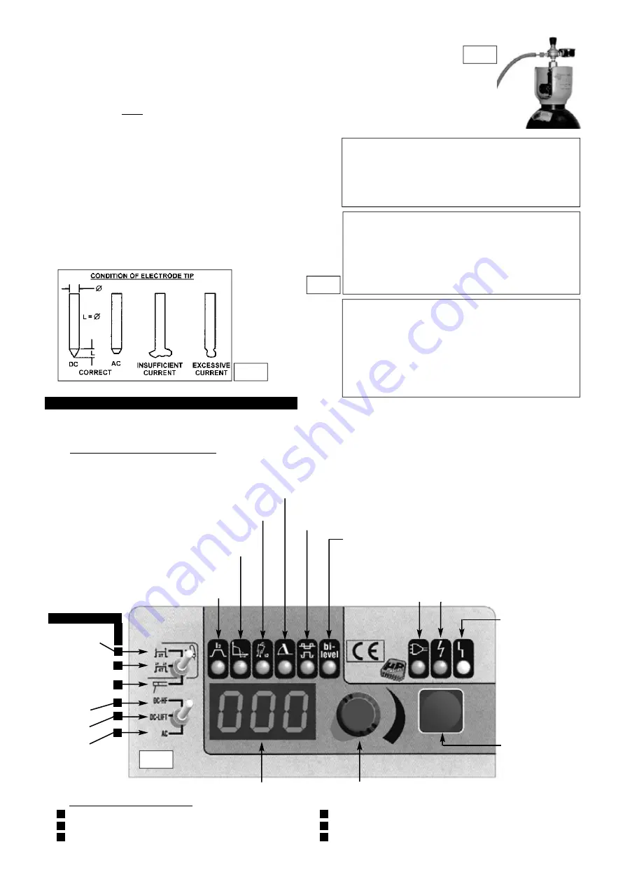
4. CONTROL PANEL
4.0
The TIG175/HF is microprocessor controlled allowing the setting of a high number of parameters enabling the operator to make an optimal weld under
most conditions and with most materials. When the machine is switched off the last active parameters are retained and recalled when the machine is
switched on again.
4.1
SELECTION OF WELDING PARAMETERS.
4.1.1 The 6 main welding parameters are grouped above the main LED display and each symbol has an associated single LED. Use the parameter selection
button to the right of the knob to step through the parameters until you reach the one you wish to adjust. The parameter is active when the LED below the
symbol is illuminated. The value to be adjusted will appear in the main display. Adjust the value by using the rotary encoder knob to the right of the display.
4.2
SELECTION OF WELDING MODES.
Use the two miniature toggle switches on the left hand side of the control panel to select the required welding mode.
TIGAC 2 step weld cycle . . . . . . . . . . . . . . . . .see section 5.6.1
TIGAC 4 step weld cycle . . . . . . . . . . . . . . . . . . . .see section 5.6.2
ARC welding with stick electrode . . . . . . . . . . . . .see section 7.0
DC HF start . . . . . . . . . . . . . . . . . . . . . . . . . . . . . . . .see section 6.7
DC Lift start . . . . . . . . . . . . . . . . . . . . . . . . . . . . .see section 6.8
AC Welding . . . . . . . . . . . . . . . . . . . . . . . . . . . . . . .see section 5.9
ALARM CONDITION
(Yellow LED) See main
display for two types of
alarm as described below.
AL.1
Fault in primary
power supply; power
supply voltage is outside
the required range.
AL.2
One of the
safety thermostats has
cut in due to the
machine overheating.
The machine will return
to normal operation
automatically when
it has cooled down.
OUTPUT VOLTAGE
(Green LED)
POWER SUPPLY
VOLTAGE
(Green LED)
BI-LEVEL WELDING
Adjusts the level of the base current in relation to
the main current that has been set. Works only in TIG 4 step weld cycle.
Varies from a maximum value equal to the main current to a minimum value
equal to 30% of the main current To switch off the bi-level function turn the
encoder knob anticlockwise until the display shows off. See section 5.6.3
BALANCE
Sets a percentage ratio in TIG AC modes between the time that the current is
EN ( electrode negative ) and the period of the square waveform in AC operation. Setting
can vary between 20% and 90%. ( See section 5.7.1 and also fig.10 )
CURRENT DOWN SLOPE
This setting reduces the current gradually at the end of welding and can be varied from 0.1 to 10 seconds. ( See section 5.3 )
POST GAS TIME
Sets post gas time from 0.1 to 25 secs. See section 5.2
ARC FORCE
Regulates the value of the arc force current and only
applies to ARC welding with a stick electrode. Arc force is
expressed as a percentage of the welding current. See section 7.6
MAIN CURRENT
This setting is measured in AMPS and
can vary from 5 to 140 for ARC welding and 5 to 160 in
TIG DC or TIG AC. The value represents the average
welding current for DC and the effective welding current
for AC
TIG AC
2 step weld cycle
TIG AC
4 step weld cycle
ARC welding with
stick electrode
DC HF Start
DC Liftstart
AC Welding
ENCODER KNOB
for setting parameter values
MAIN DISPLAY
shows selected parameter values and alarm conditions
PARAMETER
SELECTION BUTTON
Steps through the
available parameters.
Single illuminated
LEDs indicate the
selected parameter.
3.6
PREPARATION AND CHOICE OF ELECTRODE .
In order to produce a good
weld it is important to choose an electrode of the correct diameter for the current
to be used. For a general guide to the settings to be used with particular
diameters of electrodes please refer to the adjacent tables. The electrode will
normally protrude from the ceramic nozzle by 2 to 3mm but in order to gain
access to inaccessible areas such as internal corners the electrode can be made
to protrude by up to 6mm. The chosen electrode should be sharpened axially on
a grinding wheel as indicated in the diagram below. The tip should be
perfectly concentric in order to avoid arc deviations. The condition of the
electrode should be regularly inspected to maintain it in peak condition.
3.7
PREPARATION OF THE WORKPIECE.
For a good weld it is important that the
workpiece is thoroughly cleaned so that no oxides, oil, grease or solvents remain
on the surface of the material.
fig 7
fig 9
TIG WELDING PARAMETERS FOR STAINLESS STEEL (DC)
Thickness Current Electrode
Nozzle
Argon Filler Rod
(mm)
( A )
(diam mm) (diam mm) ( L/min ) (diam mm)
0.3 - 0.5
5 - 20
0.5
6.5
3
---
0.5 - 0.8
15 - 30
1
6.5
3
---
1
30 - 60
1
6.5
3 - 4
1
1.5
70 -100
1.6
9.5
3 - 4
1.5
2
90 - 110
1.6
9.5
4
1.5 - 2.0
3
120 - 150
2.4
9.5
6
2 - 3
4
140 - 190
2.4
9.5 - 11
5 - 6
3.0
TIG
WELDING PARAMETERS FOR DEOXIDATED COPPER (DC)
Thickness Current Electrode
Nozzle
Argon Filler Rod
(mm)
( A )
(diam mm) (diam mm) ( L/min ) (diam mm)
0.3 - 0.8
15 - 60
0.5 - 1
6.5
4
---
1
50 - 100
1.0
9.5
6
1.5
TIG WELDING PARAMETERS FOR ALUMINIUM (AC)
Thickness Current Electrode
Nozzle
Argon Filler Rod
(mm)
( A )
(diam mm) (diam mm) ( L/min ) (diam mm)
1
30 - 40
1 - 1.6
6.5
4 - 6
1.2 - 2
1.5
60 - 85
1.6
9.5
4 - 6
2
2
70 - 90
1.6
9.5
4 - 6
2
3
110 - 160
2.4
11
5 - 6
2
3.5
CONNECTING THE GAS
3.5.1 When using Argon gas fit the Bull Nose Adaptor supplied, to the cylinder with a spanner.
3.5.2. Fit the gas regulator onto the Bull Nose Adaptor. ( see fig.6 )
3.5.3 Using the clear tubing supplied connect the regulator to the gas inlet on the back of the inverter ( see fig.5a - 3 ). Hold the
tubing securely in place on each connector by using the worm drive clamps supplied.
3.5.4 Open the regulator before opening the cylinder valve. Test for leaks.
3.5.5. Set the gas flow to suit the welding parameters required. See WELDING PARAMETER TABLES below for general guidance.
3.5.6 If necessary the gas flow can be adjusted during welding using the regulator knob.
fig 6
fig 8
TIG175HF - 1 - 061003
A
A
B
B
C
C
D
D
E
E
F
F
WELDING MODES


