5.
TIG WELDING PRINCIPLES & FEATURES
5.0
If you have no welding experience we recommend that you seek training from an expert source before using this equipment. Good TIG welding may only be
achieved with continued supervised practice.
Before commencing welding read the safety instructions in Section 1.
5.1
TIG WELDING - GENERAL PRINCIPLES OF OPERATION.
( For a concise explanation of the facilities of the TIG175/HF refer to Section 4. Control Panel )
The TIG welding procedure uses the heat produced by an electric arc, struck and maintained between a Tungsten electrode and a workpiece to soften and
fuse the workpiece metal, usually in conjunction with a suitable filler rod. The electrode is held in an insulated torch which transmits the welding current to
the electrode. The torch also has a gas connection which allows inert Argon gas to be dispensed from a ceramic nozzle surrounding the electrode. This
produces a shroud of gas around the welding process which protects the electrode and molten weld pool from oxidation.
5.2
POST GAS TIMING FACILITY. A post - gas time can be set from 0.1 to 25 seconds to allow the protective Argon gas to continue to flow after the arc is
extinguished to protect the finished weld whilst it is cooling.
5.3
CURRENT DOWN SLOPE FACILITY. A time can be set to reduce the current gradually at the end of a weld process and can be varied from 0.1 to 10 seconds.
5.4
On thin pre-prepared material ( up to 1mm ) welding can be achieved without a filler rod by fusing the edges of the metal together. Most welding however will
be done using a filler rod to complete a joint. This rod is melted in the weld pool but should not make contact directly with the electrode.
It is essential that
operators wear adequately insulated gloves to protect themselves from the heat of the welding process, metal spatter and any direct contact with the electrode.
5.5
The tungsten electrode will be consumed during the welding process but at a very slow rate. The tip of the electrode must be periodically inspected and
re-ground if necessary to ensure continued efficient welding. See fig.7 Condition of electrode tip.
5.6
TORCH PUSH BUTTON CONTROL FUNCTIONS.
The torch push button can be used to control the welding current in a number of ways depending on
your welding requirements. ( Select one of the following options from the control panel. )
5.6.1
Two step weld cycle.
In this mode the push button is pressed and held down to strike the arc and to continue welding. When the end of the weld is
reached the push button is released and the arc is switched off. The post-gas facility can be used in this mode if required.
5.6.2
Four step weld cycle.
This mode allows you to complete long welds without having to continuously hold down the torch button. The push button is first held
down which strikes the arc and then provides a current with a value which is 25% of the main current setting as long as the button continues to be held
down. Once the push button is released the current rises to the welding current previously set and stays at this level even though the push button has been
released. If the button is then pressed and held down again the current will decrease according to the current down slope setting until it is once again 25% of
the preset current and remain there whilst the button is held. When the button is released the current is turned off and the post gas time begins. ( If initiated. )
5.6.3
Four step weld cycle with bi-level function.
This function is available in four step mode only and allows the welding current to be changed from one
presettable value to another using the torch button while the arc remains struck. To use this function select the bi-level parameter and set the desired value
as a percentage of the main current. (This can vary from a maximum value equal to the main current setting to a minimum value equal to 30% of the main
current.) Initiate the welding process for the four step weld cycle as described above. During the course of welding at the main current you have set ( with
the torch button released ) the current can be made to dip down towards the set base current and back again by momentarily pressing and releasing the
torch button.This function can be used as a sequence of rapid presses which can help to control heat and penetration during difficult welds. At the end of a
rapid sequence of presses when the button is released, the current will remain at the main weld current set and the welder will continue to function as
previously described in four touch mode.
5.7
ALTERNATING CURRENT TIG WELDING MODE.
This type of welding is particularly suited to welding metals such as aluminium and magnesium
which form a protective and isolating oxide coating on their surfaces. By inverting the polarity of the welding current, it is possible to break the superficial
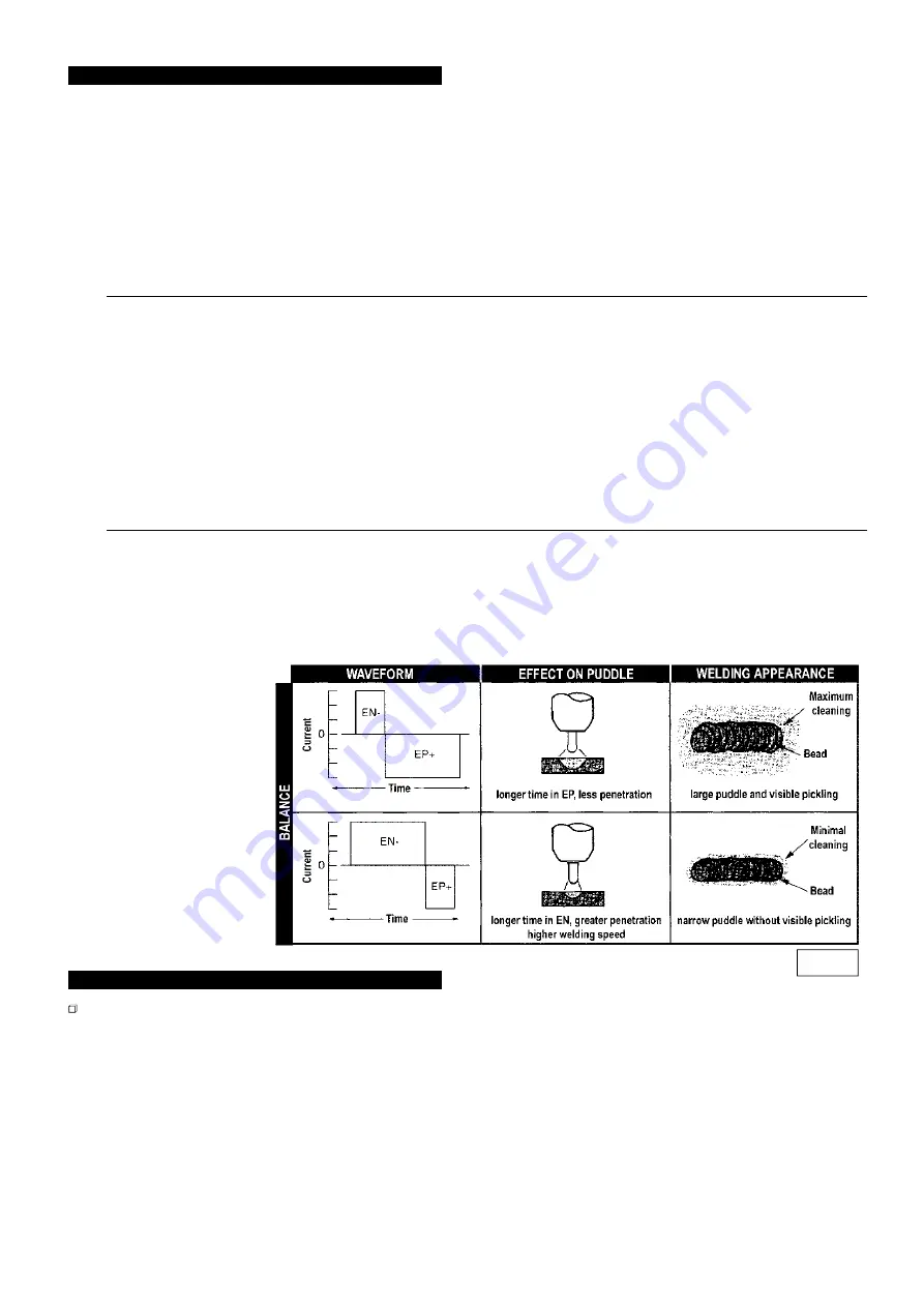
oxide layer by means of a mechanism called ionic sandblasting. The voltage of the tungsten electrode alternates between positive (EP) and negative (EN).
During the time the electrode is positive the oxide is removed from the surface by a cleaning/pickling action thereby allowing puddle formation. During the
time the electrode is negative the maximum heat is applied to the workpiece to allow welding to take place. This feature is controlled by the balance parameter.
5.7.1 BALANCE is represented as a percentage and can be set from 20% to 90%. ( See fig.10 )
Greater values of balance will result in faster welding, deeper penetration, more concentrated arc, narrower weld pool and limited heating on the electrode.
Smaller values will allow a better cleaning of the part. Too small a value of balance will result in an enlargement of both the arc and the deoxidated area, plus
overheating of the electrode
leading to the formation of a
ball on its face and
consequent difficulty in
striking the arc and
indiscriminate arc direction.
Too large a value of balance
will result in a dirty weld pool
with dark inclusions.
5.7.2 The various settings
described in TIG DC
operations are also possible
in AC mode. ( i.e. HF or LIFT
start, 2 or 4 Step torch
operation. ) The welding
procedures described for DC
TIG are also valid for AC TIG.
5.7.3 Refer to fig.8 for relevant
data regarding welding
aluminium. It is
recommended that a pure
tungsten electrode is used for
aluminium ( coded green ).
6.
TIG WELDING PROCEDURE
p
WARNING: use welding head shield to protect eyes and avoid exposing skin to ultraviolet rays given off by electric arc. Wear safety welding gauntlets.
If difficult welds are to be performed and the welding parameters are unknown, it is advisable to carry out several trial runs on test pieces in order to
determine the right welding current and gas flow.
6.1
SWITCH ON
the welder only when you are satisfied that the welder is correctly connected and the work to be done is fully prepared.
Setting the controls.
( Select the welding mode and adjust the appropriate parameters for the intended welding task. )
6.2
Set the required gas flow using the knob on the gas regulator.
6.3
Select either the two step welding mode or the four step welding mode using the miniature toggle switch on the left of the front panel.
6.4
Set the post gas time if required.
6.5
Set the current down slope if required.
6.6
Set the welding current required.
6.7
Striking the arc. ( HF facility )
Press and hold the torch button bringing the electrode tip to within 2 - 3mm of the workpiece. The arc will be struck by high
frequency impulses. When the arc is established, form a molten pool on the workpiece, introduce the filler rod and proceed along the joint. When the arc is
difficult to strike, despite the presence of gas and visible high frequency discharges it is not advisable to carry on for any length of time. Before continuing,
check the integrity of the electrode surface and tip and if necessary regrind the tip.
6.8
Striking the arc. ( LIFT facility )
Lightly touch the workpiece with the electrode tip. Push the torch button fully and lift the electrode with a delayed
action thereby obtaining the striking of the arc with the same value as that previously set. Proceed to weld as described above.
6.9
To cease welding release the torch button.
6.10
SWITCH OFF
the welder and turn off the gas at the cylinder valve.
TIG175HF - 1 - 061003
fig 10


