


5.2.
DRAWINg FLUID INTO ThE EXTRACTOR
5.2.1.
Before operating the extractor you must press the pressure release button (see fig.1-1) to dissipate any vacuum or pressure remaining in
the tank from previous use. The pressure gauge needle should return to the zero position.
NOTE:
The extractor should never be stored with any vacuum or pressure left within the tank.
5.2.2.
Set up the unit for oil extraction as described in Sections 5.1.1 to 5.1.4 so that the extractor probe is inserted into the vehicle’s
dipstick tube. The other end of the extractor probe should be joined to the extension tube with the adaptor provided and the extension
tube should be connected to the inlet/outlet coupling (See fig.1-13).
NOTE:
extraction via the dipstick tube should only be done whilst the oil is warm.
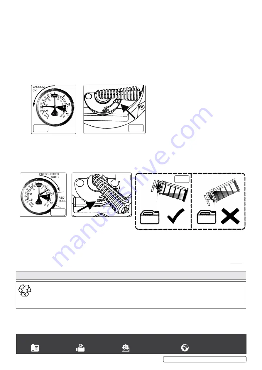
5.2.3.
move the In/oUT valve lever to the In position as shown in fig.4.
5.2.4.
Fold out rod foot rest as shown in fig.1-6.
5.2.5.
To commence suction place your foot over the foot rest to steady the unit and start to pump the handle up and down through its full
travel. The needle on the gauge should move anti-clockwise from the zero position as shown in fig.3.
5.2.6.
As you pump up and down, the tank will begin to fill. When the tank is full the auto shut off mechanism will operate and the pump handle
will lock up. To return the handle to the down position hold down the pressure relief button and push the handle down.
5.2.7.
Remove the extractor probe from the dipstick tube and replace the dipstick.
5.3.
EXPELLINg FLUID FROM ThE EXTRACTOR
5.3.1.
Place the end of the extension tube into a suitable container ensuring that it is large enough to hold the volume of liquid in the extractor’s
tank.
5.3.2.
move the In/oUT valve lever to the oUT position as shown in fig.6.
5.3.3.
Fold out rod foot rest as shown in fig.1-6.
5.3.4.
To empty the extractor’s tank place your foot over the foot rest to steady the unit and start to pump the handle up and down
through its full travel. The needle on the gauge should move clockwise from the zero position as shown in fig.5. If excess pressure is
created the needle will move into the red zone and the pressure will be automatically relieved.
5.3.5.
As you pump up and down, the tank will begin to empty.
Continue pumping until all fluid has been expelled.
When the tank is empty, press the pressure relief button to
dissipate any residual pressure remaining in the tank. If extracted oil has cooled down and thickened we recommend that it should be
poured from the extractor tank.
5.3.6.
Remove the outlet bung from the pouring spout as described in Sections 4.1 and 4.2.
5.3.7.
Pour the oil from the tank as shown below (fig.7).
DO NOT
over tip the unit as this will result in inconsistent flow form the tank.
5.3.8.
Insert the bung into the spout and turn fully anti-clockwise to lock in position for future use.
WARNINg
! When the extractor’s tank contains liquid that is under pressure
DO NOT
remove or insert the extension tube connector into the
inlet/outlet fitting as this may result in a sudden discharge of liquid that could be dangerous. Always press the pressure relief button before
connecting or disconnecting the extension tube.
Original Language Version
© Jack Sealey limited
fig.3
fig.4
fig.5
fig.6
fig.7
sealey group, kempson Way, suffolk Business Park, Bury st Edmunds, suffolk. IP32 7AR
01284 757500
01284 703534
sales@sealey.co.uk
www.sealey.co.uk
ENVIRONMENT PROTECTION
Recycle unwanted materials instead of disposing of them as waste. All tools, accessories and packaging should be sorted, taken to
a recycling centre and disposed of in a manner which is compatible with the environment. When the product becomes completely
unserviceable and requires disposal, drain any fluids (if applicable) into approved containers and dispose of the product and fluids
according to local regulations.
Note
: It is our policy to continually improve products and as such we reserve the right to alter data, specifications and component parts without prior
notice. If you require documentation for alternative versions, please email or call our technical team on technical@sealey.co.uk or 01284 757505.
Important: no liability is accepted for incorrect use of this product.
Warranty
: Guarantee is 12 months from purchase date, proof of which is required for any claim.
Parts support is available for this product. Please email sales@sealey.co.uk or telephone 01284 757500
TP6905.V2, TP6906.V2 Issue:3 (3) 26/04/19


