background image

38


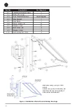
Ref No.

Description

No. Required

2.1

140W Solar Panel & Frame

1

2.2

Battery Box Cage

1

2.3

Post, 150x150 minimum

Client Supplied

2.4

Steel Support

1

2.5

Steel Brace

1

2.6

Screw, 12mm x 75

12

2.7

Washer, 12mm

12

2.8

Bolt, 10mm x 25

4

2.9

Washer, 10mm

4

2.10

Self Locking Nut, 10mm

4

Figure 2. Installation of Solar Panel & Battery Box Cage


Alternative setup, using 2 x 85W 

panels.

Lantern duty cycle and intensity will 

determine the size and quantity of 

solar panels and batteries.

Summary of Contents for SL-300-1D5 Series

Page 1: ...SL 300 1D5 Series 13 21 NM Marine Lanterns V1 3 INSTALLATION SERVICE MANUAL ...

Page 2: ...Manual Launch January 2015 Y Chambers 1 1 Power supply design considerations Peak Current March 2016 Y Chambers 1 2 Power Supply Design Considerations update August 2018 Y Chambers 1 3 Addition of Lantern Status Chart September 2019 M Nicholson ...

Page 3: ...peration Page 24 Read Page 24 Flash Code Page 25 Flash Code Numbers Page 25 Intensity Page 25 Battery Status Page 26 Lux Page 26 Error Acknowledge Indication Page 27 Configuration Settings Page 27 Operational Mode Advanced Users Page 28 Lantern Status Chart Page 29 SL 300 Series Lantern Power Consumption Page 30 Power Basics Page 30 Thermal Management Page 31 Lantern data Page 32 Thermal limit ope...

Page 4: ...ite is the world s fastest growing manufacturer of marine aids to navigation We employ leading mechanical optical hardware software engineers to create innovative products to service the needs of our customers worldwide and offer the widest range of solar powered LED lanterns in the marketplace Electronics Sealite employs leading in house electronic engineers in the design and development of softw...

Page 5: ... configuration The small form factor provides minimal wind loading and convenient handling delivering significant advantages over traditional larger lens stack assemblies High Efficiency The long range lanterns produce a class leading intensity to power ratio making them highly efficient suitable for solar power solutions Advanced PC or IR Programming Sealite s convenient PC Configuration Tool or ...

Page 6: ...nal GSM GPS antenna 200mm bolt pattern for ease of installation Optional bird deterrent spikes Precision upper lower heat sinking UV stabilised acrylic lens Marine grade two part epoxy coating Ø 373 378 302 154 PCD 200 30 º 30 º ...

Page 7: ...ultiple LED optic Mounting 3 4 hole 200mm bolt pattern Height mm inches 302 12 Width mm inches 373 14 Mass kg lbs 18 5 40 Product Life Expectancy Up to 12 years Environmental Standards Ice Loading Rated to withstand 225g m2 Temperature Range 40 C to 60 C Wind Exposure Rated to withstand 140knots Humidity 0 100 condensing Driving Rain at 45 from vertical Waterproof IP68 Certifications Immunity EN 6...

Page 8: ...del Optional GSM GPS antenna 200mm bolt pattern for ease of installation Optional bird deterrent spikes Precision upper middle lower heat sinking UV stabilised acrylic lens Marine grade two part epoxy coating 154 30 30 ...

Page 9: ... Multiple LED optic Mounting 3 4 hole 200mm bolt pattern Height mm inches 496 19 Width mm inches 373 14 Mass kg lbs 38 5 85 Product Life Expectancy Up to 12 years Environmental Standards Ice Loading Rated to withstand 22kg m2 Temperature 40 C to 60 C Wind Exposure Rated to withstand 140knots Humidity 0 100 condensing Driving Rain at 45 from vertical Waterproof IP68 Certifications Immunity EN 61000...

Page 10: ...kaged within foam in a carton and shipped to you PLEASE NOTE The programming cable provided is suitable for use with PC s If you require connection to your notebook laptop a Serial Port to USB cable may need to be purchased Please check that ALL of these components are included with your order and contact your Sealite representative as soon as possible if anything is missing Product Components ...

Page 11: ...r displaying the PC Configuration Tool Saving the Programming Software to Computer Hard Drive Connect the USB drive to your computer Navigate to the USB drive folder Copy the file called LanternConfig exe and the dll files Navigate to the hard drive location where you would like to save this program and then right mouse click and select paste A copy of the programming software will now be saved to...

Page 12: ...12 Image 1 Sealite PC Configuration Tool ...

Page 13: ...ng the Lantern to the Computer Plug the Bulgin connector end of the programming cable into the lantern PC Programming Port and the serial port end of the cable into your computer serial communication port RS232 E PLEASE NOTE The programming cable provided is suitable for use with desktop PC s If you require connection to your notebook laptop a Serial Port to USB cable may need to be purchased 3 Es...

Page 14: ...nder the headings Version Lantern Summary If this error occurs please check the following Reconnect the lantern to the computer Check that the lantern power supply has sufficient charge eg battery is charged and then reconnect it to the lantern Re run the Sealite PC Configuration Tool and follow the information in step 3 The connection should now become established The Sealite lantern is now ready...

Page 15: ...eration Mode Flash Code and Intensity Tabs for a description of these parameters Name A user defined name comprising alphanumeric characters and can be typed into dialogue box and by pressing and stored within the lantern s non volatile memory by pressing the Write Name button LED Colour A generic picture of the lantern model and colour that the software tool is communicating with is displayed in ...

Page 16: ...talled is disabled Always On The daylight sensor is disabled and the lantern operates according to the set flash character and intensity levels Dusk till Dawn The daylight sensor is monitored and the lantern will only operate at night time Day and Night The daylight sensor is monitored and the lantern will operate according to the set flash character and intensity levels for Day Twilight and Night...

Page 17: ...an advanced user mode and typically only used if the lantern is to be used as a special navigational aid such as emergency wreck mark All Default on setting All LEDs are operated in unison and configured by the Operation Mode Flash Code and Intensity Tabs Reset By clicking Reset the factory set default parameters are restored ...

Page 18: ...IR remote control section for valid flash characters Sync Offset This panel is used to set a fixed delay to the commencement of the flash character The built in GPS receiver and advanced software of the Sealite synchronised lanterns allow for the adoption of SeaFlare channel marking a unique system that cascades the flash synchronisation of channel lanterns in a uni or bi directional flash pattern...

Page 19: ... can be set by either by defining the operating range of the lantern in nautical miles or by entering a desired peak candela or a percentage of maximum peak intensity level If an intensity level is selected that is beyond the specification of the lantern the entered figure will be displayed in red coloured text and the lantern will be configured to its maximum ...

Page 20: ...s The lantern will only commence operation once the input voltage has exceeds the OK voltage level The three thresholds Flat Low and OK are user definable Temperature The SL 300 utilises two temperature sensors One that monitors the temperature of the master board and one that monitors the temperature of the driver board Each sensor has two configurable temperature thresholds High and OK There are...

Page 21: ...ngle LED failure the lantern can be configured to trigger the internal alarm relay which in turn can be connected externally to trigger other devices such as redundant light source Light Sensor The SL 300 lantern has its own internal light sensor and whose day twilight night thresholds are defined in LUX These levels can be customised by entering in separate values as a measure of LUX The default ...

Page 22: ...that is output via the serial communications port every 10 seconds Typically this message is processed by an externally installed AIS module however by itself is a quick summary of the lantern operating status This detail is also displayed on the INFO tab AIS Report ...

Page 23: ...sh once The user should wait until the light responds to each keypress before pressing another key If there is no response to the keypress after 3 seconds it has not been detected by the light and the key can be pressed again If an invalid key is detected the light will flash quickly 5 times In this case the command will have to be restarted T C T C Read Lux Flash Code Intensity Battery Status Tes...

Page 24: ...to the Flash Code tables to match the IR Remote flash number to the Flash Code The light flashes the current intensity setting 1 flash for 25 2 for 50 3 for 75 and 4 for 100 The light flashes the current battery status The light flashes the sunset level in Lux followed by a 2 second gap followed by the sunrise level Levels are in the range of 1 to 9 T C T C R L FC I B 3 4 5 6 7 8 9 0 1 2 T C T C R...

Page 25: ...racter is changed the peak intensity is automatically adjusted T C T C R L FC I B 3 4 5 6 7 8 9 0 1 2 Flash Code This key sets the flash code on the light Example Key sequence This sets the flash code to value 123 The light responds by flashing the flash code value Flash Code Numbers The lamp flashes numbers as follows Hundreds Tens Ones A value of 125 will be flashed as 1 flash followed by a dela...

Page 26: ...100 lux The light will turn on when its surroundings are darker The light responds by acknowledgement with a long flash Level Sunset Dusk Sunrise Dawn 1 64 100 2 100 150 3 150 240 4 240 370 5 370 600 Default Factory Preset L I B 8 9 0 T C T C R L FC I B 3 4 5 6 7 8 9 0 1 2 T C T C R L FC I B 3 4 5 6 7 8 9 0 1 2 T C T C R L FC I B 3 4 5 6 7 8 9 0 1 2 Battery Status This function reads the battery s...

Page 27: ...tensity switches and is then set to 50 using the IR Remote Control the intensity setting will change to 50 If the intensity is then set to 75 using the switches the new intensity value will be 75 In order to change intensity settings using the IR Remoter Control the lamp must be powered The lamp can detect a change in switch settings if they are changed while the light is powered down Example 2 Th...

Page 28: ...or via the GSM module if fitted In Always On mode the daylight sensor is disabled and the lantern will remain ON In Standby mode the lantern is turned off and the daylight sensor is disabled This mode does not affect the operation of the GSM module In Dusk to Dawn the daylight sensor is enabled Always on mode Standby mode Dusk to Dawn mode T C T C B I 1 T C T C B I 2 T C T C B I 3 ...

Page 29: ...al ON Lantern is re syncing with GPS The lantern re sync s with the GPS every 15 minutes Flashing 2 x Quick Flashes every 11 seconds Normal ON Lantern is a Hard Wire Synchronisation Slave Red LED Lantern Status Lantern Comment OFF Normal ON Normal Battery Voltage Flashing once every 1 6 seconds Battery Voltage is 24 25V or 48 50V ON Battery Voltage is between 24 25V Battery Voltage is between 48 5...

Page 30: ...tern In an instant of time this is the maximum power the lantern will consume It is determined when all a lantern s features are on and the LEDs intensity is at 100 c Average Power is a measure of Power over a period of time In raw terms it expressed as Average Power Watts Peak power Watts x MULTIPLIER where the MULTIPLIER Flash Character duty cycle x Intensity level d The SL 300 lanterns intensit...

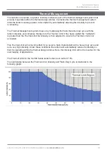
Page 31: ...intensity and compares this figure to the Thermal Limit If the figure called the multiplier is greater than the Thermal Limit the intensity is then adjusted to ensure the Thermal Limit is not exceeded This Thermal Limit will come into effect if you select a flash characteristic with a heavy duty cycle and set a very high intensity Under these conditions the lantern will automatically reduce its in...

Page 32: ...r the entire day Irelay 16 0 38 16 0 38 Consumption when energised Igsm average 13 0 31 13 0 31 Consumption over the entire day SL 300 Series SL 300 1D5 1 W SL 300 1D5 2 W Peak power W 384 768 Max power thermal limit 37 5 37 5 Max average power at thermal limit W 132 264 Peak intensity cd 94 400 188 800 Voltage range VDC 24 to 48 24 to 48 Thermal limit operation Automatically the lantern calculate...

Page 33: ...sity cd is determined as 30 988cd 3 Using IALA E 200 4 the Peak Intensity cd is 35 120cd 4 Calculate the desired Intensity step setting 0 to 32 100 based upon the SL 300 1 W Maximum Peak Intensity cd 35 120 cd 94 400 cd 32 steps 12 rounded up 5 Calculate the MULTIPLIER 33 3 duty cycle 12 32 100 12 5 6 Compare this to the Max Power Thermal Limit for a SL 300 1D5 W 37 5 The MULTIPLIER 37 5 and is be...

Page 34: ...n for operating multiple lanterns from a single power supply solution 1 PV Power Systems These systems generally comprise of a 1 or more PV panels a solar regulator and storage battery Batteries such as marine grade SLAs are very tolerant of fast switch high peak currents as they electrically behave like a large smoothing capacitors As detailed in IALA 1067 Solar sizing depends on a number of fact...

Page 35: ...ply or battery For lanterns programmed to Dusk to Dawn operation setting cover lantern with a dark cloth or jack in darkness for more than 1 minute After this time the lantern will activate Next check that the lantern is flashing to the required flash code and intensity If the settings are correct disconnect from the 24V power supply or battery If the settings are incorrect following the Programmi...

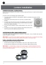
Page 36: ...ating washes fitted and the lantern fixed into position with additional washes and nuts LANTERN INSTALLATION MAINS POWER SOLAR The Sealite SL 300 may be installed with connection to mains power or as a complete solar powered system available from Sealite IMPORTANT the SL 300 must be installed appropriately where the lantern is not blocked by buildings trees or other shadows that may affect the vis...

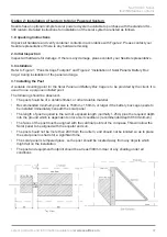
Page 37: ... for the Solar Panel and Battery Box Cage is to be provided by the client It is usual to use a purpose installed post The following should be observed The post should be of a durable timber or other durable material Recommended minimum post size is 150mm x 150mm or larger if the battery box cage needs to be installed immediately beneath the solar panel The length of post required is the sum of exp...

Page 38: ...eel Support 1 2 5 Steel Brace 1 2 6 Screw 12mm x 75 12 2 7 Washer 12mm 12 2 8 Bolt 10mm x 25 4 2 9 Washer 10mm 4 2 10 Self Locking Nut 10mm 4 Figure 2 Installation of Solar Panel Battery Box Cage Alternative setup using 2 x 85W panels Lantern duty cycle and intensity will determine the size and quantity of solar panels and batteries ...

Page 39: ...ttery box a Open the battery box cage door and place the battery case Ref 3 1 into the cage with the hinge of the case adjacent to the hinge of the cage b Open the battery case and lower the battery into the case ensuring the battery terminals are upright c Insert one bolt Ref 3 3 with a washer Ref 3 4 under the head through each of the battery terminals d Place the red eye connector over the tail...

Page 40: ...MPORTANT it is important to work with the team at Sealite when determining the quantity and size of both batteries and solar panels for this lantern Duty cycle intensity and local solar conditions are important factors to take into consideration when building a solar powered battery supply Sealite solar marine lanterns will give years of trouble free service if installed correctly initially Please...

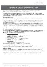
Page 41: ... a number of earth stations using atomic clocks as the time base Continuous self checking ensures that the light will continue to run in synchronisation First time power up Dusk to Dawn On first time power up the GPS wakes up and obtains a position fix 1min and then remains on for up to 12 5mins for leap seconds data After which the GPS is turned off and will reawaken at a period that is set by th...

Page 42: ... is in idle mode to reduce power consumption Time data continues to be updated once per second The microprocessor will automatically exit the idle mode as soon as dark conditions are detected Dark Operation When dark conditions are detected the light Checks for valid time data and is turned on after a delay based on the current time and the length of the selected flash code If valid time data is n...

Page 43: ...Configx xx exe note version number may vary 3 Extract the executable file 4 Connect the lantern to a power source 5 Connect the lantern to the PC 6 Click COM Setup 7 Select the appropriate COM Port from the drop down menu in the Serial Port dialogue box 8 Ensure the Open Port check box is selected and Port is Open is displayed 9 Click Ok 10 Lantern should be connected and ready for programming Lan...

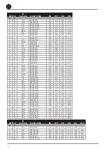
Page 44: ...ortion to the timing cycle For example 0 5 seconds on and 4 5 seconds off equals a 10 duty cycle It is best to operate at the lowest duty cycle appropriate to the actual needs of the application Recommended Rhythm for Flashing Light IALA Regions A and B MARK DESCRIPTION RHYTHM Port Hand Starboard Marks Any other than Composite Group Flashing 2 1 Preferred Channel Starboard Composite Group Flashing...

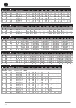
Page 45: ... 3 3 0 8 5 133 FL 5 S 0 2 4 8 4 1 65 FL 5 S 0 3 4 7 5 1 81 FL 5 S 0 5 4 5 9 5 149 FL 5 S 0 9 4 1 6 1 97 FL 5 S 1 0 4 0 SWITCH IR Controller FLASH CODE ON OFF A B 7 1 113 FL 5 S 1 5 3 5 4 2 66 ISO 5 S 2 5 2 5 8 2 130 LFL 5 S 2 0 3 0 0 3 3 OC 5 S 3 0 2 0 1 3 19 OC 5 S 4 0 1 0 2 3 35 OC 5 S 4 5 0 5 C 6 198 FL 6 S 0 2 5 8 B 5 181 FL 6 S 0 3 5 7 C 5 197 FL 6 S 0 4 5 6 8 1 129 FL 6 S 0 5 5 5 9 1 145 FL ...

Page 46: ...7 71 FL 2 8 S 0 5 1 0 0 5 6 0 8 8 136 FL 2 8 S 0 8 1 2 2 4 3 6 5 7 87 FL 2 8 S 1 0 1 0 1 0 5 0 4 C 76 OC 2 8 S 3 0 2 0 1 0 2 0 5 C 92 OC 2 8 S 5 0 1 0 1 0 1 0 F B 251 VQ 2 8 S 0 2 1 0 0 2 6 6 9 A 154 FL 2 10 S 0 4 1 6 0 4 7 6 6 7 103 FL 2 10 S 0 5 1 0 0 5 8 0 7 7 119 FL 2 10 S 0 5 1 5 0 5 7 5 6 9 105 FL 2 10 S 0 5 2 0 0 5 7 0 8 7 135 FL 2 10 S 0 8 1 2 0 8 7 2 B 9 185 FL 2 10 S 1 0 1 0 1 0 7 0 9 7 ...

Page 47: ...5 S 0 7 0 7 0 7 0 7 2 1 10 1 6 8 104 FL 2 1 15 S 1 0 2 0 1 0 5 0 1 0 5 0 1 C 28 VQ 3 15 S 0 1 0 5 0 1 0 5 0 1 13 7 4 B 75 FL 3 20 S 0 5 3 0 0 5 3 0 0 5 12 5 3 B 59 FL 3 20 S 0 5 1 5 0 5 1 5 0 5 15 5 5 B 91 FL 3 20 S 0 8 1 2 0 8 1 2 0 8 15 2 6 B 107 FL 3 20 S 1 0 1 0 1 0 1 0 1 0 15 0 SWITCH IR Controller FLASH CODE ON OFF ON OFF ON OFF ON OFF A B B F 191 VQ 4 4 S 0 3 0 3 0 3 0 3 0 3 0 3 0 3 2 3 B D...

Page 48: ...10 1 7 D 125 MO B 15 S 1 5 0 5 0 5 0 5 0 5 0 5 0 5 10 5 SWITCH IR Controller FLASH CODE ON OFF ON OFF ON OFF ON OFF ON OFF A B D D 221 Q 5 7 S 0 3 0 7 0 3 0 7 0 3 0 7 0 3 0 7 0 3 2 7 E D 237 Q 5 10 S 0 3 0 7 0 3 0 7 0 3 0 7 0 3 0 7 0 3 5 7 E 8 232 FL 5 12 S 0 5 1 5 0 5 1 5 0 5 1 5 0 5 1 5 0 5 3 5 5 F 95 FL 5 20 S 0 5 0 5 0 5 0 5 0 5 0 5 0 5 0 5 0 5 15 5 9 F 159 FL 5 20 S 0 8 1 2 0 8 1 2 0 8 1 2 0 ...

Page 49: ...SL 300 1D5 Series 13 21NM Marine Lanterns Latest products and information available at www sealite com 49 Sealite LED Light Warranty V2 2 Refer to Sealite website sealite com ...

Page 50: ...50 ...

Page 51: ...SL 300 1D5 Series 13 21NM Marine Lanterns Latest products and information available at www sealite com 51 ...

Page 52: ...ralia 61 0 3 5977 6128 Sealite Asia Pte Ltd Singapore 65 6908 2917 Sealite United Kingdom Ltd UK 44 0 1502 588026 Sealite USA LLC USA 1 603 737 1311 We believe technology improves navigationTM sealite com info sealite com ...

Reviews: