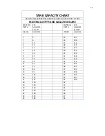
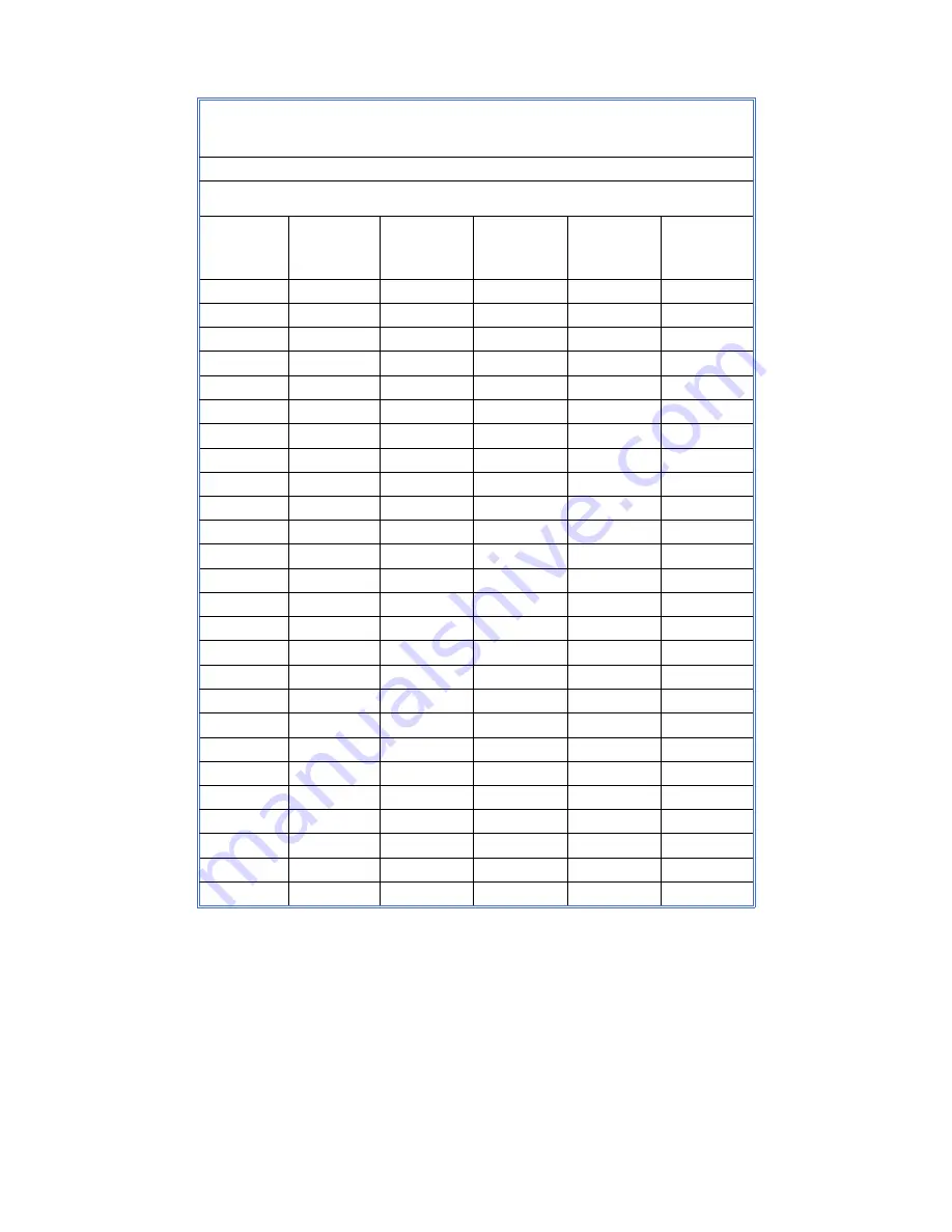
background image

21 


TANK CAPACITY CHART 

GALLONS ARE APPROXIMATE AND MAY VARY SLIGHTLY TANK TO TANK 

MATERIAL DEPTH AND GALLON VOLUME 

MATERIAL 
DEPTH 

309 
GALLONS 
41"x54" 


MATERIAL 
DEPTH 

309 
GALLONS 
41"x54" 

INCHES 

GALLONS 


INCHES 

GALLONS 


25 

197 


26 

206 

10 


27 

216 

15 


28 

225 

21 


29 

233 

28 


30 

242 

35 


31 

250 

42 


32 

258 

50 


33 

266 

10 

58 


34 

274 

11 

67 


35 

281 

12 

75 


36 

287 

13 

84 


37 

293 

14 

93 


38 

298 

15 

102 


39 

303 

16 

112 


40 

307 

17 

121 


41 

309 

18 

130 


42 


19 

140 


43 


20 

150 


44 


21 

159 


45 


22 

169 


46 


23 

178 


47 


24 

188 


48 


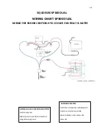
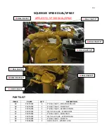
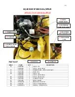
Summary of Contents for SP 300

Page 1: ......

Page 2: ...urrent SQUEEGEE_300_V2 0_APR2020 docx SP300 SQUEEGEE AND DUAL SPRAY SQUEEGEE Owner s Manual Version 2 0 Issue Date April 2020 Effective Date January 2019 Version Date Changes Approval 1 0 Original Issue 2 0 4 20 New Format and Updates DS ...

Page 3: ...NGINE 10 TO START ENGINE 10 TO OPERATE MACHINE 10 FILLING MATERIAL TANK 11 OPERATING WATER FOG NOZZLE 12 SQUEEGEE APPLICATION OF SEALER 12 MACHINE PARTS LIST SQUEEGEE SP300 13 PARTS LIST 13 MACHINE MAINTENANCE 19 MAINTENANCE SCHEDULE 19 TROUBLESHOOTING GUIDE 20 TANK CAPACITY CHART 21 MATERIAL DEPTH AND GALLON VOLUME 21 KUBOTA GAS ENGINE PARTS LIST 22 PARTS LIST FOR 1605 GAS ENGINE 22 WIRING CHART ...

Page 4: ...NER 42 CHECK BALLS 42 TROUBLESHOOTING GUIDE 43 DISASSEMBLY ASSEMBLY DIAPHRAGMS SANDPUMPER II 44 1 CHANGING THE DIAPHRAGMS 44 2 CHANGING THE DIAPHRAGMS ACTUATOR ROD 45 CHECK BALL ASSEMBLY SANDPUMPER II 46 1 SERVICING THE CHECK BALLS 46 2 SERVICING THE BOTTOM CHECK BALLS 46 OPERATION INSTRUCTION SANDPUMPER II 47 FILLING THE TANK FROM ANOTHER CONTAINER 47 APPLICATION SPRAY WAND 48 APPLICATION SPRAY B...

Page 5: ..._______________________________ Acceptance Date ________________ City _____________ State______ Zip _______ CORRESPONDENCE All Correspondence regarding this equipment as well as general correspondence should be addressed to ThorWorks Industries Inc PO Box 2277 Sandusky OH 44870 In referring to the equipment kindly state the Model Number Serial Number and any part number involved ...

Page 6: ...ed SealMaster representative Any claims for defective material or workmanship must be made prior to the expiration of thirty 30 days from the date failure occurs and in all cases prior to the expiration of the warranty period of one 1 year It is the intent of this paragraph to limit SealMaster s liability solely to the cost of replacement parts F O B factory or at the option of SealMaster to repai...

Page 7: ...quipment SealMaster offers both self propelled ride on squeegee machines and self propelled ride on the dual squeegee and spray seal coating equipment SealMaster self propelled seal coating machines are designed to mix and apply pavement sealers with or without sand SealMaster self propelled seal coating machines have set the seal coating equipment industry standards for quality performance and du...

Page 8: ... is familiar with the units operation Replace any hoses that show signs of wear fraying or splitting Be sure all fittings and joints are tight and leak proof Do not do maintenance work on the unit while in operation The unit should not be left unattended when running CAUTIONS Keep hands feet and clothing away from moving parts Do not operate the machine without all guards in place Do not point the...

Page 9: ... be the result of more serious trouble FIRE PREVENTION Avoid fire hazards such as 1 Always stop the engine when refueling do not refuel while smoking or when near an open flame or sparks 2 Always wipe up any spills immediately 3 Batteries produce explosive gases keep open flame or sparks away 4 Remove all trash or debris from the machine make sure that oily rags or other flammable materials are no...

Page 10: ...death LEARN TO BE SAFE 1 STUDY THE OPERATORS MANUAL and other pertinent information furnished with the equipment Learn your machines operating and maintenance characteristics capacities and limitations 2 Learn the location and function of all controls indicators and warning devices 3 Be familiar with the safety devices on your machine 4 Learn to recognize the machines warning and safety signals th...

Page 11: ...s damaged parts or parts out of adjustment Perform all recommended daily maintenance TRAFFIC CONTROL Proper traffic control is your responsibility Never place a Pavement sealer in an uncontrolled area Protect vehicles and pedestrians from the workplace REMEMBER ONLY YOU CAN PREVENT INJURY TO YOURSELF AND OTHERS SAFETY IS YOUR RESPONSIBILITY ...

Page 12: ... steering wheel all the way out and turn ignition switch 1 If the engine does not start repeat this procedure Use the choke moderately Allow the engine to warm up before operating 7 WARM ENGINE It should not be necessary to use the choke when the engine is warm However this may vary with each engine This will require the operator to become familiar with the unit TO OPERATE MACHINE 8 To move the ma...

Page 13: ...a proper consistent speed 11 To avoid a buildup of sand on the sides of the machine always pour sand into the center of the tank The usual amount of sand used to provide an anti skid surface or to fill porous pavement is three pounds per gallon of sealer This will vary according to the porosity of the surface you are sealing 42 CONTROL LEVER H 10 AGITATOR CONTROL VALVE 7 WATER TOGGLE SWITCH H 14 R...

Page 14: ...F SEALER 14 Lower the rear assembly valve lever H 14 by moving labeled Rear Assembly to DOWN position 15 Place your feet on the peddles Push down with the toe part of your foot to OPEN valves Press with the heel to CLOSE valves Keep sealer in a roll of 1 to 3 inches for full 90 application If you are sealing on a hill going horizontal use only the flow control valve toward the top of the hill This...

Page 15: ...AL STEM 22 P577A004 1SET SPLIT RIM ONLY 23 P354B 1 FRONT AXLE WELDMENT ASSEMBLY 35 P464A005 1 FUEL CAP 36 P579A002 5 HUB BOLT 1 2 20 37 P458A066 1 HONDA GAS ENGINE 690 CC H8 P474A078 1 MOTOR HYDRAULIC 54 P73000B066 1 GAS TANK 55 P716A005 1 HYDRAULIC COOLER WITH BYPASS 69 P953A003 1 T HANDLE LATCH 71 P1008A012 2 1 1 2 PLUG PVC OPTIONAL 4 WATER PUMP ELECTRIC 10 WATER TANK 11 SPRAY TIP H8 STEERING MO...

Page 16: ... WIRE ASSEMBLY 42 P488A002 1 CONTROL QUADCO P488A003 1 CABLE 68 P473A001 1 STEERING COLUMN H7 P936A003 1 CONTROL HYD STEERING H10 P472A019 1 AGITATOR CONTROL VALVE H14 P472A019 1 REAR ASSEMBLY UP DOWN VALVE H15 P472A019 1 REAR ASSEMBLY LEFT RIGHT VALVE 42 CONTROL LEVER H10 AGITATOR CONTROL VALVE 7 WATER TOGGLE SWITCH H14 REAR ASSEMBLY UP AND DOWN H15 REAR ASSEMBLY LEFT AND RIGHT 33 CHOKE 34 THROTT...

Page 17: ...R 1 1 4 2 BOLT H9 P474A061 1 MOTOR HYD WITH SPEED CONTROL H12 P600A005 1 CYLINDER HYD 1 3 4 X 6 51 P398A009 2 3 BUTTERFLY VALVE 56 P83000B083 1 FOOT PEDAL SUB ASSEMBLY 57 P72000I027 1 YOKE 58 P326B 2 LINKAGE ASSEMBLY 59 P83000B080 2 3 BUTTERFLY VALVE ARM 14 COUPLING 26 BEARING PLATE 27 FLANGE BEARING AGITATOR 24 SEAT H9 AGITATION MOTOR H12 CYLINDER 56 FOOT PEDAL ASSEMBLY 57 YOKE 58 LINKAGE 59 ARM ...

Page 18: ...30A057 1 JAW COUPLER SPLINE 62 P630A058 1 JAW COUPLER 63 P631A010 1 INSERT 64 P604A017 1 ACCESS COVER 65 P583A003 1 CLEANOUT COVER 66 P583A004 1 BAFFLE MOUNT 67 P1050A006 1 BREATHER FILTER CAP 70 P908A007 1 FILTER TRANSMISSION 72 P74000C019 1 DIPSTICK HYDRAULIC OIL 61 JAW COUPLER SPLINED 62 INSERT 63 JAW COUPLER 64 ACCESS COVER 60 PUMP MOUNT BRACKET 13 FILTER IN LINE FUEL H6 FLOW DIVIDER H13 OIL F...

Page 19: ...09B 1 BACKING STRIP 70 46 P459A024 1 NEOPRENE 1 2 X 6 X 94 47 P459A023 1 NEOPRENE 1 2 X 6 X 74 48 P70021C 1 SWIVEL FRAME ASSEMBLY 49 P70003 1 BOTTOM FRAME ASSEMBLY 50 P459A024 1 NEOPRENE 1 2 X 6 X 94 73 109C 1 BACKING STRIP 90 5 8 53 REAR END COMPLETE ASSEMBLY 52 CYLINDER 49 BOTTOM FRAME ASSEMBLY 48 SWIVEL FRAME ASSEMBLY 43 BOX FRAME ASSEMBLY DRAG BOX ASSEMBLY 44 BACKING STRIP 46 NEOPRENE 94 47 NE...

Page 20: ...OLE 32 P1057A002 20 LUG NUT 1 2 20 NF LOCK WASHER 20 SOCKET HD CAP SCREW 1 2 20 X 1 LG 74 P1018A017 34 NORD LOCK WASHER P513A056 5 STUD M14X1 5 DOUBLE END 5 FLANGE NUT M14X1 5 75 P1015A018 24 SOCKET HD CAP SCREW M14 1 5 X 50MM LG 76 P474A068 2 WHEEL DRIVE WITH BRAKE H4 MOTOR HYD RIGHT H3 MOTOR HYD LEFT 30 TIRE TUBE ASSEMBLY 31 SPLIT RIM 29 AGITATOR ASSEMBLY AGITATOR RUBBER BACKING STRIP 76 WHEEL D...

Page 21: ...L LEVELS CHECK HYDRAULIC OIL LEVELS CHECK GASOLINE FUEL LEVELS CHECK COOLANT LEVELS CHECK AIR CLEANER GREASE STEERING SHAFT CHANGE ENGINE OIL see manual CHANGE HYDRAULIC OIL CHANGE HYDRAULIC OIL FILTER CHANGE ENGINE COOLANT CHANGE FUEL FILTER CHANGE AIR CLEANER DRAIN WATER FROM FUEL FILTER CHECK TIRE PRESSURE CHECK V BELT CHANGE V BELT INSPECT ALL HOSES Use a good quality AW68 ASTM Grade 315 visco...

Page 22: ...PECIFICATIONS REFER TO OWNER S MANUAL OPERATING INSTRUCTIONS REFER TO OWNER S MANUAL SPARK PLUG WET DRY OR REPLACE FUEL FILTER CLOGGED REPLACE FILTER OIL LEVEL LOW FILL TO PROPER LEVEL OIL FILTER PLUGGED OR LOOSE TIGHTEN OR REPLACE OIL FILTER TRANSMISSION IS WORN NEEDS REBUILT OR REPLACED SURGE TANK PLUGGED CLEAN OUT TANK DIAPHRAGM PUMP BALL OR SEAT REPLACE AS NEEDED MATERIAL CHUNKS EMPTY TANK FLU...

Page 23: ...4 MATERIAL DEPTH 309 GALLONS 41 x54 INCHES GALLONS INCHES GALLONS 1 2 25 197 2 6 26 206 3 10 27 216 4 15 28 225 5 21 29 233 6 28 30 242 7 35 31 250 8 42 32 258 9 50 33 266 10 58 34 274 11 67 35 281 12 75 36 287 13 84 37 293 14 93 38 298 15 102 39 303 16 112 40 307 17 121 41 309 18 130 42 19 140 43 20 150 44 21 159 45 22 169 46 23 178 47 24 188 48 ...

Page 24: ...01 0 P458G019 V BELT FAN 16282 9701 3 P458G018 COOLING FAN 16285 7411 0 P458G020 FAN DRIVE PULLEY 16697 7428 0 P458G010 EXHAUST MANIFOLD EG522 1231 3 KUBOTA MODEL WG1605 G E3 four cylinder water cooled gasoline engine rated at 49 6 gross intermittent horsepower at 3000 rpm Equipped with a 12 volt electrical system with 40 amp alternator 10 foot extension harness ECU mounted key switch Controls Inc...

Page 25: ... FUSE YELLOW IGNITION GREEN GROUND BLACK FROM HOUR METER Blue to fan Relay Black on Rectifier to Black Ground White on Starter to power Bolt Starter Solenoid to male Plug Yellow stripe black stripe on Rectifier butt connect to Yellow stripe black stripe on Engine Black from Engine butt connect HYDRAULIC OIL COOLER FAN MOTOR Red to relay red Black butt connect then to black on relay then to ground ...

Page 26: ...INE IGNITION HYD COOLER FAN RELAY WATER HYDRAULIC OIL COOLER FAN MOTOR Red to relay red Black butt connect then to black on relay then to ground FAN RELAY SWITCH Red from 20 amp fuse at battery 87 Red to red on fan motor 86 Black to black on fan motor 85 Blue 30 ...

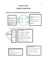
Page 27: ...25 HYDRAULIC FLOW CHART ...

Page 28: ...26 SQUEEGEE SP300 DUAL SPRAY SQUEEGEE APPLIES TO SP 300 SP 300 DUAL PLANETARY GEAR HUB HUB MAINTENANCE ...

Page 29: ...eat 21 COLD ENGINE Turn key to RUN on control panel engine display 74 located on the control panel Let the display go into its cycle then turn key to CRANK Allow the engine to warm up before operating TO OPERATE MACHINE 22 To move the machine forward push control lever 1 forward SLOWLY until your desired speed is reached To move the machine in reverse pull the control lever to neutral completely s...

Page 30: ...28 SQUEEGEE SP300 DUAL SPRAY 1 CONTROL LEVER CABLE CONTROL LEVER CABLE IN NEUTRAL POSITION 74 CONTROL PANEL ENGINE DISPLAY IGNITION KEY OFF RUN CRANK ...

Page 31: ...consistent speed 25 To avoid a buildup of sand on the sides of the machine always pour sand into the center of the tank The usual amount of sand used to provide an anti skid surface or to fill porous pavement is three pounds per gallon of sealer This will vary according to the porosity of the surface you are sealing 1 CONTROL LEVER CABLE 7 AGITATOR CONTROL VALVE 10 WATER TOGGLE SWITCH 9 REAR ASSEM...

Page 32: ...ON OF SEALER 28 Lower the rear assembly valve lever 9 by moving the lever to DOWN position labeled Rear Assembly 29 Place your feet on the peddles Push down with the toe part of your foot to OPEN valves Press with the heel to CLOSE valves Keep sealer in a roll of 1 to 3 inches for full 90 application If you are sealing on a hill going horizontal use only the flow control valve toward the top of th...

Page 33: ...P476A004 2 BEARING CONE 32 P476A005 2 BEARING OUTER RACE 39 P449A010 1 TIP SPRAY 65 10 1 4 OPTIONAL 40 P464A005 1 FUEL CAP 65 P1008A012 2 1 1 2 PLUG PVC OPTIONAL 66 P360E 1 SHAFT 67 P345D 1 WELDMENT STEERING FORK 68 P354B 1 FRONT AXLE WELDMENT ASSEMBLY 69 P579A002 5 HUB BOLT 1 2 20 70 P574A002 1 TUBE WITH METAL STEM 71 P73000B066 1 GAS TANK 29 WATER TANK WATER PUMP ELECTRIC 39 SPRAY TIP 27 STEERIN...

Page 34: ...ONTROL 72 P461A001 1 PANEL FUSE HOLDER OPTIONAL 73 P595A009 1 FUSE 25 AMP ABC OPTIONAL 74 P458B422 1 CONTROL PANEL ENGINE DISPLAY 75 P50273B 1 SPRAY WAND ASSEMBLY 76 P449A004 1 SPRAY TIP 80 70 3 8 NPT STEEL 77 P397A010 1 SPRAY WAND VALVE 3 4 BALL STEEL 78 P754B026 1 3 4 HOSE X 75 LONG 1 CONTROL LEVER CABLE 7 AGITATOR CONTROL VALVE 10 WATER TOGGLE SWITCH 72 PANEL FUSE HOLDER 73 FUSE 25 AMP 9 REAR A...

Page 35: ... 1 LID GASKET 46 P50147D 1 LID ASSEMBLY 51 P30003D 1 SURGE TANK 79 P498A004 1 1 TO 1 1 4 KEYED SOLID COUPLING 80 P83000B083 1 FOOT PEDAL SUB ASSEMBLY 81 P72000I027 1 YOKE 82 P326B 2 LINKAGE ASSEMBLY 83 P83000B080 2 3 BUTTERFLY VALVE ARM 119 P50147B009 1 BASKET STRAINER COMPLETE ASSEMBLY 15 BEARING PLATE 79 COUPLING 14 FLANGE BEARING AGITATOR 22 SEAT 21 AGITATION MOTOR 13 CYLINDER 80 FOOT PEDAL ASS...

Page 36: ...P OUT 54 P397A002 1 2 BALL VALVE RECIRCULATION 55 P397A001 1 3 4 BALL VALVE WAND HOSE 57 P397A002 1 2 BALL VALVE MAIN FEED 58 P397A001 1 3 4 BALL VALVE WATER FLUSH 59 P397A002 1 2 BALL VALVE PUMP IN 84 P398A003 1 CHECK VALVE WATER FLUSH 54 BALL VALVE 2 50 BALL VALVE 2 49 BALL VALVE 2 59 BALL VALVE 2 57 BALL VALVE 2 55 BALL VALVE 3 4 58 BALL VALVE 3 4 84 CHECK VALVE 3 4 ...

Page 37: ...LTER OIL P909A002 1 FILTER HEAD SMALL 85 P458B203 1 FILTER INLINE FUEL 86 P583A003 1 CLEANOUT COVER 87 P583A004 1 BAFFLE MOUNT 88 P1050A006 1 BREATHER FILTER CAP 89 P908A007 1 FILTER TRANSMISSION 90 P74000C019 1 DIPSTICK HYDRAULIC OIL 85 FILTER IN LINE FUEL 38 OIL FILTER FILTER HEAD SMALL 24 OIL FILTER FILTER HEAD LARGE 33 TRANSMISSION 34 PUMP HYD 88 FILTER CAP 86 CLEANOUT COVER 87 BAFFLE MOUNT 89...

Page 38: ... TIP 80 70 3 8 NPT STEEL 91 P70001G 1 BOX FRAME ASSEMBLY 92 P70001F 1 DRAG BOX ASSEMBLY 93 P109D 1 BACKING STRIP 91 3 4 94 P109B 1 BACKING STRIP 70 95 P70021C 1 SWIVEL FRAME ASSEMBLY 96 P70003 1 BOTTOM FRAME ASSEMBLY 97 109C 1 BACKING STRIP 90 5 8 19 REAR END COMPLETE ASSEMBLY 20 CYLINDER 96 BOTTOM FRAME ASSEMBLY 95 SWIVEL FRAME ASSEMBLY 91 BOX FRAME ASSEMBLY 92 DRAG BOX ASSEMBLY 93 BACKING STRIP ...

Page 39: ...574A002 2 TUBE 103 P1057A002 20 LUG NUT 1 2 20 NF LOCK WASHER 20 SOCKET HD CAP SCREW 1 2 20 X 1 LG 104 P1018A017 34 NORD LOCK WASHER 105 P1015A018 24 SOCKET HD CAP SCREW M14 1 5 X 50MM LG 106 P513A056 5 STUD M14X1 5 DOUBLE END 5 FLANGE NUT M14X1 5 18 WHEEL DRIVE HUB 18 MOTOR HYD LEFT 18 MOTOR HYD RIGHT 101 TIRE WHEEL ASSEMBLY 17 TIRE SPLIT RIM 102 TUBE 98 AGITATOR ASSEMBLY 99 AGITATOR RUBBER 100 B...

Page 40: ...ESSURE CONTROL 53 P666A004 1 PUMP SPEED CONTROL 56 P711A004 1 PUMP PRESSURE GAUGE 62 P694A002 1 CARTRIDGE VALVE 63 P694A001 1 SOLENOID 12 VOLT COIL 64 P600A007 1 SAND PUMPER II CYLINDER ASSEMBLY 47 SAND PUMPER II COMPLETE ASSEMBLY 48 PUMP TOGGLE SWITCH 56 PUMP PRESSURE GAUGE 53 PUMP SPEED CONTROL 52 PUMP PRESSURE CONTROL 64 SAND PUMPER II CYLINDER ASSEMBLY 62 CARTRIDGE VALVE 63 SOLENOID 12V COIL ...

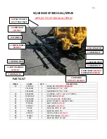
Page 41: ...39 SQUEEGEE SP300 DUAL SPRAY SANDPUMPER II SANDPUMPER II ...

Page 42: ...966A068 4 GASKET MANIFOLD 120 P966A065 4 CHECK BALL NEOPRENE 121 P966A072 2 SEAT ASSEMBLY 122 P966A067 1 SUCTION PORTING FLANGE 123 P966A073 2 FLANGE THREADED 124 P966A070 2 O RING 125 P966A069 1 MANIFOLD 126 P966A071 2 SEALING RING 127 P1014A034 4 HEX HEAD SCREW 1 2 13 X 1 3 4 128 P1018A005 4 SPLIT LOCK WASHER 1 2 129 P1021A002 12 LOCK NUT 1 2 13 130 P1020A005 8 HEX NUT 1 2 13 131 P1025A001 8 EXT...

Page 43: ...OVER PLATE BRACKET 146 P966A091 2 FOOT MOUNT 147 P1010A001 1 REDUCER BUSHING 3 8 TO 1 4 148 P560A022 1 HYDRAULIC TEE 3 8 MMF 149 P560A007 1 HYDRAULIC FITTING 3 8 150 P560A031 1 HYDRAULIC FITTING 06 NPT X 08 JIC 151 P751A006 1 HOSE ADAPTER 3 8 NPT X 5 8 HOSE 152 P461A001 1 FUSE HOLDER 153 P443A001 1 TOGGLE SWITCH 154 P711A004 1 PRESSURE GAUGE 2000 PSI 155 P1017A008 2 FLAT WASHER 3 4 156 P595A001 1 ...

Page 44: ...ck balls are made of solid neoprene and are 2 1 4 inches in diameter It is recommended that the check balls be replaced every two years SUCTION STRAINER 1 The SandPumper II material pump system comes with a large one gallon basket strainer The strainer basket has 1 8 hole mesh CHECK BALLS 1 For most efficient pumping performance it is recommended check balls and ball seats are in good working orde...

Page 45: ... BUT WILL GO UP AND DOWN WHEN TURNING PUMP PRESSURE CONTROL VALVE RELIEVE HYDRAULIC PRESSURE REMOVE SOLENOID UNSCREW CARTRIDGE FROM BODY PRESS IN ON PLUNGER IT SHOULD MOVE APPROXIMATELY 3 16 INCH AND SPRING BACK TO ITS ORIGINAL POSITION PRESSURE GAUGE SHOWS PRESSURE BUT WILL NOT GO UP AND DOWN WHEN TURNING PUMP PRESSURE CONTROL VALVE CONTAMINATION IN PUMP PRESSURE CONTROL VALVE CONSULT WITH FACTOR...

Page 46: ...ch on the flats that are machined on cylinder rod CAUTION If you use a pliers or any kind of clamping device on the cylinder rods the rod seals will be destroyed when the pump shifts g While holding the 1 wrench on the cylinder rod put a 1 1 8 wrench to the bolt head that is welded to the outer support plate Turn counter clockwise to loosen remove completely from cylinder rod h Remove the inner su...

Page 47: ...orque wrench set at 40 ft lbs and tighten the bolts diagonally until the flanges are drawn down evenly Set the flange gap to the measurement you took in step a 2 CHANGING THE DIAPHRAGMS ACTUATOR ROD When changing the side that the actuator rod comes from follow steps 1 a thru 1 e Peel back the diaphragm the actuator rod is welded to an arm that fits around the cylinder rod Put your wrench on this ...

Page 48: ... on the stainless steel seat assembly 121 sand may cut grooves there replace if necessary Remove the seat and lift out the bottom set of balls If the seat needs replaced go to step 2 d Scrape off the old gaskets and install new gaskets 119 e If there is any damage to the check balls 120 replace as necessary f Reinstall the manifold and tighten the 6 locknuts g Put grease in the grove in the piping...

Page 49: ...ng drawn from the container and is filling up the machine s tank 5 Monitor the level by looking in through the lid and using your tank chart as a guide for how much material you want to add When done close pump in valve 59 and pump speed control valve 53 Turn off pump toggle switch 48 Detach the suction hose 6 Add the desired amount of water and additives Engage the agitator control valve 7 to the...

Page 50: ...e To increase pressure turn the pressure control knob 52 clockwise or in To decrease pressure turn the knob counterclockwise or out NOTE The thickness of the product determines how much pressure is needed to get the proper spray intensity It may be necessary to run the pressure higher than 800 psi 5 Remove the spray hose and wand from the side of the machine and stretch out the hose Open wand hose...

Page 51: ...e 58 3 Turn on pump toggle switch 48 Open pump speed control valve 53 about three turns 4 To flush out the spray wand open 3 4 ball valve 55 Open the lid on the machine place the wand in the tank and open the wand valve It is not necessary to run it till you see clear water as this is a waste However you need enough water to push the sand out of the hose otherwise it lays in the coils and plugs th...

Page 52: ...RECIRCULATION VALVE 2 50 PUMP OUT VALVE 2 49 SPRAY BAR VALVE 2 59 PUMP IN VALVE 2 57 MAIN FEED VALVE 2 55 WAND HOSE VALVE 3 4 58 WATER FLUSH VALVE 3 4 84 CHECK VALVE 3 4 44 STRAINER BASKET 46 BASKET STRAINER LID ASSEMBLY 45 LID GASKET ...

Page 53: ...DPUMPER II COMPLETE ASSEMBLY 48 PUMP TOGGLE SWITCH 56 PUMP PRESSURE GAUGE 53 PUMP SPEED CONTROL 52 PUMP PRESSURE CONTROL 7 AGITATOR CONTROL VALVE 21 AGITATION MOTOR WITH SPEED CONTROL SPEED CONTROL 41 SPRAY BAR ASSEMBLY 42 1 2 BALL VALVE ...

Page 54: ...L 112 P600A005 1 CYLINDER HYD 1 3 4 X 6 STROKE 113 P472A025 1 HYDRAULIC CYLINDER ASSEMBLY 114 P693A033 1 CARTRIDGE VALVE 115 P694A006 1 SOLENOID 12 VOLT COIL 116 P443A015 1 SPRAY BAR TOGGLE SWITCH 117 P461A006 1 FUSE HOLDER 118 P595A012 1 FUSE 15 AMP ATO 108 SPRAY BAR ASSEMBLY COMPLETE 113 HYDRAULIC CYLINDER ASSEMBLY 114 CARTRIDGE VALVE 115 SOLENOID 12V COIL 111 SPRAY TIP 80 70 109 CUSTOM CUT 3 4 ...

Page 55: ...If you have a water tank spray bar water pump and fog spray run RV antifreeze thru these also 3 Disconnect the battery and take it inside A battery charging maintainer will assure that it lasts through the off season 4 Cover the engine with a plastic bag 5 Cover the cap on the hydraulic tank also around each locking cap 6 If any cylinder rods are exposed put a thin layer of grease on them 7 In the...

Page 56: ...L SUCTION LINE P458B032 1 FILTER OIL KUBOTA ENGINE SP300 DUAL P458B173 1 FILTER OIL HONDA ENGINE SP300 LIST FOR SQUEEGEE MACHINE SP300 SP300 DUAL SPRAY PART QTY DESCRIPTION P966A090 1 SAND PUMPER II REBUILD KIT P449A004 5 SPRAY TIP 80 70 3 8 NPT STEEL P459A013 2 AGITATOR RUBBER P459A024 2 NEOPRENE 1 2 X 6 X 94 P459A023 1 NEOPRENE 1 2 X 6 X 74 P50147B009 1 BASKET STRAINER COMPLETE ASSEMBLY P514A002...

Reviews: