


45
plate and slide it onto the bolt coming through the
diaphragm, mating the groove to the diaphragm bead.
Thread the bolt into the cylinder rod, when snug you can
adjust all the diaphragm beads to fit the grooves in the
support plates and other flanges.
l.
Insert the 1” wrench onto the cylinder rod.
m.
Take a torque wrench set at 85 ft.-lbs. and tighten the outer
support plate bolt.
n.
Put the sealing ring #126, back on the check ball assembly if
it came off with the chamber onto the check ball assembly
studs and then insert all the flange bolts. Take a torque
wrench set at 40 ft.-lbs. and tighten the bolts diagonally
until the flanges are drawn down evenly. Set the flange gap
to the measurement you took in step a.
2.
CHANGING THE DIAPHRAGMS: – ACTUATOR ROD
When changing the side that the actuator rod comes from,
follow steps 1.a thru 1.e. Peel back the diaphragm, the
actuator rod is welded to an arm that fits around the
cylinder rod. Put your wrench on this arm rather than the
flats on the cylinder. Follow the remaining steps.
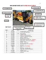
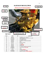
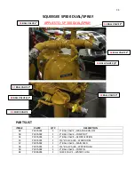
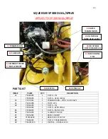
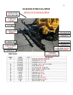
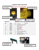
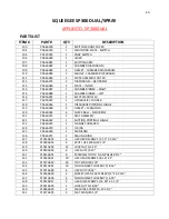
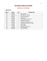
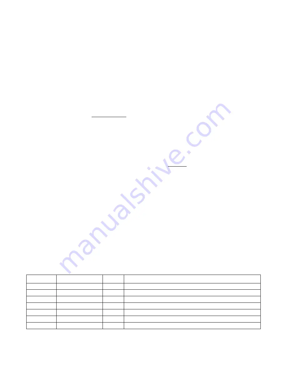
PARTS LIST: USE
P966A090
REBUILD KIT
ITEM #
PART#
QTY.
DESCRIPTION
120
P966A065
4
CHECK BALL – NEOPRENE
119
P966A068
4
GASKET – MANIFOLD
124
P966A070
2
O RING
126
P966A071
2
SEALING RING
121
P966A072
2
SEAT ASSEMBLY
112
P966A074
2
DIAPHRAGM – NEOPRENE
109
P966A083
2
GASKET - CHAMBER DIAPHRAGM
Summary of Contents for SP 300
Page 1: ......
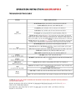
Page 27: ...25 HYDRAULIC FLOW CHART ...
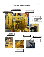
Page 41: ...39 SQUEEGEE SP300 DUAL SPRAY SANDPUMPER II SANDPUMPER II ...


