background image

DO2 INSTRUCTIONS

Seametrics • 253.872.0284 

Page 20 seametricscom

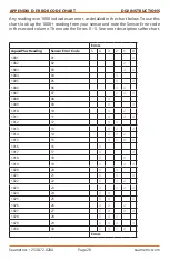
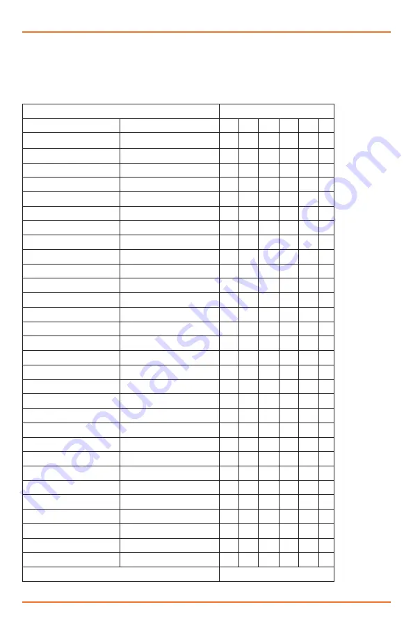
Any reading over 1000 indicates an error, as detailed in the chart below. To use this 

chart, look up the 1000+ reading from your sensor and note the Sensor Error code 

in the second column. Then note the Errors 0 – 5. See error descriptions after chart.


Errors

Aqua4Plus Reading

Sensor Error Code

5

4

3

2

1

0

1001

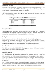
01

1002

02

1003

03

1004

04

1005

05

1006

06

1007

07

1008

08

1009

09

1010

10

1011

11

1012

12

1013

13

1014

14

1015

15

1016

16

1017

17

1018

18

1019

19

1020

20

1021

21

1022

22

1023

23

1024

24

1025

25

1026

26

1027

27

1028

28

1029

29

1030

30

Errors

APPENDIX D: ERROR CODE CHART

Summary of Contents for DO2

Page 1: ...PROUDLY MADE IN THE USA C e rtified Compa n y ISO ISO 9001 DO2 DO2 Dissolved Oxygen Smart Sensor and Datalogger Instructions ...

Page 2: ......

Page 3: ...ng 7 Reports 9 Maintenance 12 Troubleshooting 13 Erratic Readings 13 Grounding Issues 13 Appendix A Technical Specifications 14 Appendix B Field Calibration 16 Appendix C Reading the Seametrics DO2 Sensor via Direct Read 17 Reading Via Modbus 17 Setting Baud Rate 17 Reading Via SDI 12 18 Appendix E Error Code Chart 20 Limited Warranty Disclaimer Seametrics DO2 Dissolved Oxygen Sensor 23 1997 2016 ...

Page 4: ...data on a variety of time intervals The internal microprocessor runs on 12 VDC and automatically turns the sensing unit on and off as needed to conserve power Initial Inspection and Handling Upon receipt of your smart sensor inspect the shipping package for damage If any damage is apparent note the signs of damage on the appropriate shipping form After opening the carton look for concealed damage ...

Page 5: ...se with spreadsheets or databases Refer to the Aqua4Plus software manual for details on installing and using Aqua4Plus Using the Sensor Without Aqua4Plus Most users will use the sensor with Seametics Aqua4Plus software However this sensor is quite versatile allowing you to do the following Read via the Modbus protocol using your own software Read via SDI 12 protocol Display readings on a panel met...

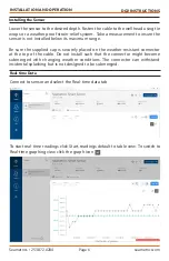
Page 6: ...re the supplied cap is securely placed on the weather resistant connector at the top of the cable Do not install such that the connector might become submerged with changing weather conditions The connector can withstand incidental splashing but is not designed to be submerged INSTALLATION AND OPERATION Real time Data Connect to sensor and select the Real time data tab To start real time readings ...

Page 7: ...k the button located next to the Single button in the Real Time tab This will permanently save this real time data set to your Reports database Data Logging Select Set Up Logging from the sensor screen If there are no files currently on the sensor you ll see the Set Up Logging button active under the Data Files tab as well as in the upper menu Once files have been started logged on the sensor they...

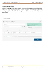
Page 8: ...D OPERATION Set Up Logging Window Here you will name your data file and set up the recording interval and duration of each logging phase Select your desired recording interval and duration for each phase Aqua4Plus 2 0 will display the available memory at the bottom of the window ...

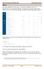
Page 9: ...older on your PC as well See Program Settings for default data folder location In the main view you ll see a list of reports sorted by date size or file name as selected here You can also search reports by keyword using the search box Click on a report to bring up the report details Reports are displayed in graphing view by default You can zoom to specific sections by selecting a section with you ...

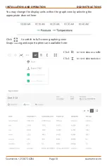
Page 10: ...ATION AND OPERATION Click to view data as a table Click to view data statistics Click to switch to full screen graphing view Graph saving and export options are available here You may change the display units within the graph view by selecting the appropriate channel here ...

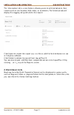
Page 11: ...t Click Export to export the report as a csv file or a4d file for distribution or use in 3rd party software Click Delete to delete the report from Aqua4Plus 2 0 You can also import a4d files from compatible sensors into Aqua4Plus 2 0 by clicking at the top of the Reports screen A Word About Units Readings from the Multi Parameter Sensor can be displayed in various units such as degrees Celsius or ...

Page 12: ...ors can be provided The connectors used by Seametrics are not submersible but are designed to be splash resistant DO Window Cleaning During deployment the sensing window on the DO2 may collect debris or growth Heavy debris growth can affect the accuracy of the DO readings over time Periodically check the window and clean if necessary Note the DO window is very sensitive and prone to scratching DO ...

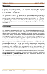
Page 13: ... by lightning powerlinesurges orfaultyequipment Withoutapropergroundingsystem a power spike will find the path of least resistance to earth ground whether that path is through sensitive electronic equipment or the person operating the equipment In order to ensure safety and prevent equipment damage a grounding system must be used to provide a low resistance path to ground When using several pieces...

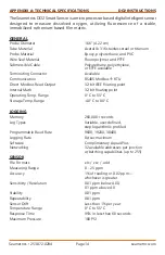
Page 14: ...5 Modbus RTU Direct Modbus Read Output 32 bit IEEE floating point Internal Math 32 bit floating point Operating Temp Range 0 C to 55 C Storage Temp Range 40 C to 80 C LOGGING Memory 260 000 records Log Types Variable user defined step logarithmic profiled Programmable Baud Rate 9600 19200 38400 Logging Rate 8x sec maximum Software Complimentary Aqua4Plus Networking 32 available addresses per junct...

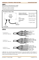
Page 15: ...wn Blue Shield may be green 12 VDC Vaux Modbus D Not used Modbus D Not used SDI 12 Signal 12 VDC Gnd Earth ground POWER External Power Pack Required 9 15VDC Seametrics Power Pack described below Other power options available Contact Seametrics for details Enclosure Material Polycarbonate 1P67 Enclosure Dimentions 5 5 x 3 1 x 2 6 14 x 7 9 x 6 6 cm excluding connec tors Power Supply 12VDC 8 AA cells...

Page 16: ...ta you want and then erase the session before continuing Place the DO2 sensor in your reference solution allow a few minutes for temperature to stabilize Obtain the DO saturation using an alternate method then select the calibration button Enter the saturation in the reference box next click Calibrate While the DO2 is calibrating you ll see this Once complete close the calibration window and check...

Page 17: ...r equipment uses one based addressing you will need to add one to the register addresses Register addresses for DO2 Sensor Zero Based One Based Temp on board 62592 62593 Pressure 62594 62595 Power 62596 62597 DO 62598 62599 Temp on probe 62600 62601 Power On Function In order to save power the power to the sensing probe on the DO2 is normally off even when the DO2 sensor itself is powered The sens...

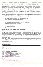
Page 18: ... value of 0 zero Turns power off Retains last reading If you Cannot Write to the Power On Register If you are reading your device using a meter or other device that cannot write the Power On but simply takes readings on a specified schedule be sure to set the polling interval to less than 7 5 seconds This will ensure that the sensing probe is always powered up and readings should be fresh and stab...

Page 19: ...616 3 9829 crc cr lf read temperature on board pressure power DO a D0 a 19 1374 crc cr lf read temperature on probe Concurrent measurement a C a 0045 cr lf request all measurements a D0 a 23 1374 14 9829 12 1616 3 9829 cr lf read temperature on board pressure power DO a D0 a 19 1374 cr lf read temperature on probe Concurrent measurement with CRC a CC a 0045 cr lf request all measurements w CRC a D...

Page 20: ...ror code in the second column Then note the Errors 0 5 See error descriptions after chart Errors Aqua4Plus Reading Sensor Error Code 5 4 3 2 1 0 1001 01 1002 02 1003 03 1004 04 1005 05 1006 06 1007 07 1008 08 1009 09 1010 10 1011 11 1012 12 1013 13 1014 14 1015 15 1016 16 1017 17 1018 18 1019 19 1020 20 1021 21 1022 22 1023 23 1024 24 1025 25 1026 26 1027 27 1028 28 1029 29 1030 30 Errors APPENDIX...

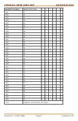
Page 21: ...1032 32 1033 33 1034 34 1035 35 1036 36 1037 37 1038 38 1039 39 1040 40 1041 41 1042 42 1043 43 1044 44 1045 45 1046 46 1047 47 1048 48 1049 49 1050 50 1051 51 1052 52 1053 53 1054 54 1055 55 1056 56 1057 57 1058 58 1059 59 1060 60 1061 61 1062 62 1063 63 1128 Unable to communicate with sensor APPENDIX D ERROR CODE CHART ...

Page 22: ...oating damage 1 Main photodiode negative excessive electrical noise or damage 2 Reference photodiode saturated circuit or sensor coating damage 3 Reference photodiode negative excessive electrical noise or damage 4 Temperature error thermistor is damaged 5 Temperature error temperature is out of range APPENDIX D ERROR CODE CHART ...

Page 23: ...ein In the event that equipment is altered or repaired by the Buyer without prior written approval by the Seller all warranties are void Equipment and accessories not manufactured by the Seller are warranted only to the extent of and by the original manufacturer s warranty THE FOREGOING WARRANTIES ARE IN LIEU OF ALL OTHER WARRANTIES WHETHER ORAL WRITTEN EXPRESSED IMPLIED OR STATUTORY IMPLIED WARRA...

Page 24: ...DO2 INSTRUCTIONS Seametrics 19026 72nd Avenue South Kent Washington 98032 USA P 253 872 0284 F 253 872 0285 1 800 975 8153 seametrics com LT 14406r8 20190115 1 15 2019 LIMITED WARRANTY DISCLAIMER ...

Reviews: