Precision Flow Measurement
An ON
I
CON Brand
Electrical
Quick Start Guide
AC Power w/Pulse (A1X/A2X)
for: iMAG 4700r / AG3000r
253.872.0284 seametrics.com
Wiring
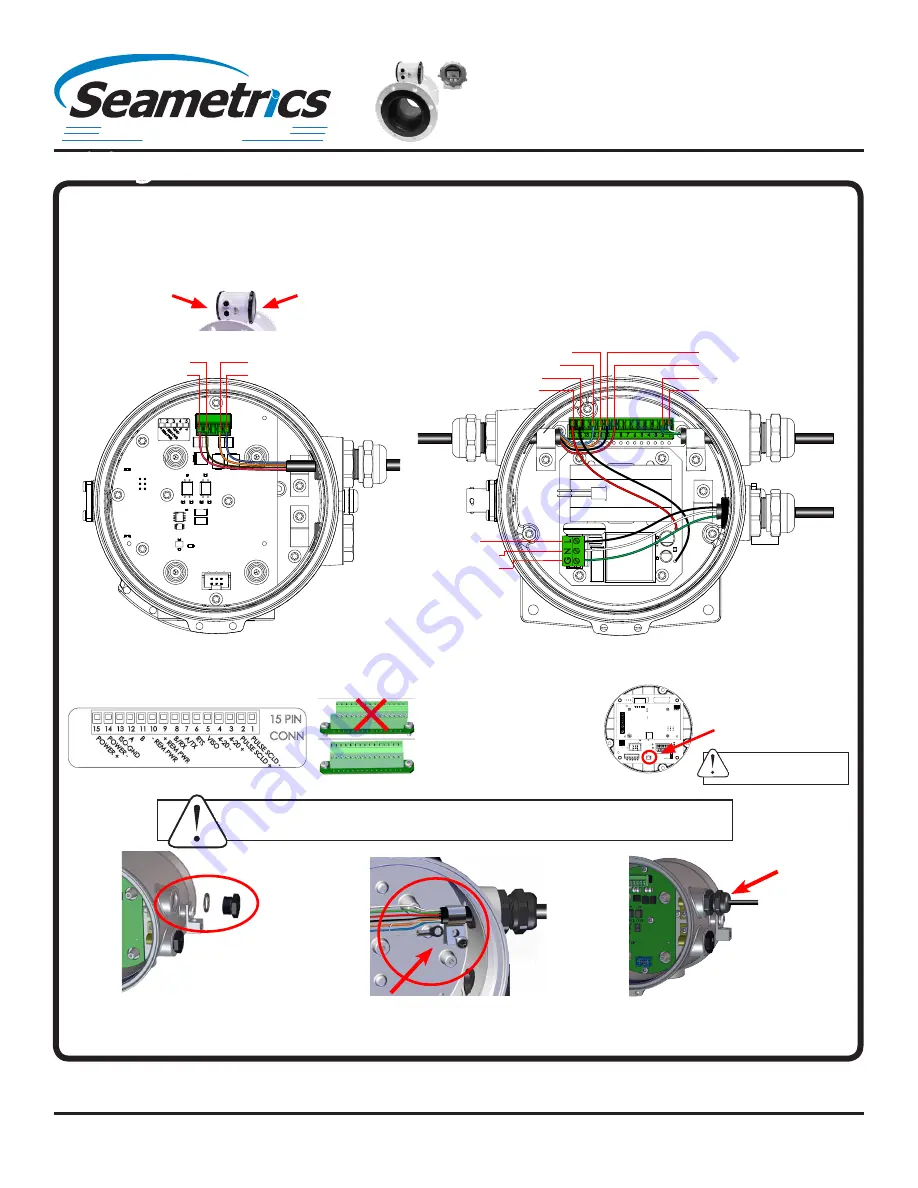
Black (Line)
White (Neutral)
Green (Ground)
Black (R) -Remote Pwr: pn10
Red (R) +Remote Pwr: pn9
Green (C1) Pulse+: pn2
White (C1) Pulse-: pn1
Orange (R) Remote B: pn11
Blue (R) Remote A: pn12
Black (Internal): pn14
Red (Internal): pn15
C1
R
AC
Orange (R) Remote B: pn4
Blue (R) Remote A: pn5
R
Black (R) -Remote Pwr: pn2
Red (R) +Remote Pwr: pn1
C1 = power/output cable
AC = AC power cable
R = remote cable
Refer to the
Mechanical Quick Start Guide
or the complete instruction manual for details on mechanical installation.
Remote Meter
Remote Display
Remote Display:
Remove the 3 screws holding the display
assembly and remove it from the meter. Remove the 15 pin
screw connector from its bag. Install the wires through the
cable ports into the 15 pin screw connector in their respective
locations. Plug the 15 pin screw connector into its socket.
Be
sure all pins align properly and that the connector has not
slipped to one side.
Refer to the complete manual for further
details.
Remote Meter:
Unscrew the user access lid and remove it.
Remove the 5 pin screw connector from its socket. Install the
wires through the cable port into the 5 pin screw connector in
their respective locations. Plug the 5 pin screw connector into its
socket. Refer to the complete manual for further details.
Plug the backup
battery cable into the
back of the display
assembly.
Be sure all pins align
properly and that the
connector has not slipped to
one side.
User access lid
Front panel—do
not open
WARNING: Improper sealing of glands or cables will invalidate any warranty.
Remove plug & o-ring. Insert
cable gland/strain relief. Feed
cable through cable gland.
CRITICAL!
Torque cable gland sealing
nut to 22 in-lbs.
Clamp cable with strain relief
clips. Attach drain wire lug to
bracket post.
WARNING: BACKUP BATTERIES
ARE NOT INTENDED AS A
PRIMARY POWER SOURCE


