INPUTS/OUTPUTS and OPERATION
Battery Power.
The iMAG 4600 meter can come configured
with two replaceable 3.6V lithium ‘D’ batteries. In this
configuration, the only option/output is the scaled pulse
output which comes standard. The scaled output for the
battery powered option has a maximum frequency of 10Hz,
with a fixed pulse width of 10ms. Be sure to set your P value
such that the meter will function properly over the flow range
in your application.
See the tech bulletin on this topic for
more details.
The sample rate of the meter is user selectable
through the SAMP tab in the meter’s sub-menu. Sample
periods of 0.2, 0.33, 1, 3, 5, 15, 30, and 60 seconds can
be selected. Larger sample periods will yield longer battery
life but slower response time. Care must be taken to select
a sample period that us suitable for your application. See
the table on the next page for the expected battery life as a
function of sample period.
Pulse Output Connection.
When the second OID code
character is “P”, refer to the “
Digital Output Application”
diagrams on page 12 for recommended pulse output
connections to external equipment. Since this is an isolated
output, the external equipment must include a dc power
source to regenerate the pulse from the open-collector
output (transistor equivalent of a contact closure). A pull-up
or pull-down resistor may be needed if not included in the
user equipment as shown in the diagrams. Both the power
source and resistor may be supplied internally in some
types of control and monitoring devices. If not, as for most
PLC discrete input modules, they must be added externally
at the module input terminals. Pulse output rate in volume
units/pulse is user-settable via the SET P tab on the meter’s
setup menus.
Analog Output (4-20mA) Connection.
When the second or
third OID code character is “L” or “H”, refer to the “
Analog
Output Application”
diagram on page 12 for 4-20mA current
loop output connections to external analog input devices.
Since the meter’s analog output is isolated and passive, loop
power must be supplied externally as shown. (In addition, an
external resistor R
L
will be needed to convert the loop current
to voltage for voltage-only input devices.) The meter’s loop
transmitter minimum voltage drop is 6Vdc (8Vdc with HART)
which, with wiring resistance and loop power supply voltage,
will determine the maximum resistance for R
L
. The flow rates
corresponding to 4 and 20mA are user-settable via the SET
4 and SET20 tabs on the meter’s setup menus.
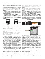
(Optional) Setup and Connection to a HART Network.
The
HART protocol, rev.7.5, allows for a Polling address of 0-63.
The default value in the iMAG is 0. To change the Polling
address, use iMAG menu HPOLL to set the Polling address.
To get to this menu, move to the EXIT tab and tap the
Hold
Tap
+
4 times. This will bring up another menu page
containing the tab HPOLL. Use the
Hold
Tap
+
to select the
Polling address.
A minimum of 250 ohms of loop resisitance must be present
in order for the HART modem to correctly and reliably
demodulate FSK voltage. With this in mind, the maximum loop
resistance* for the iMAG HART interface cannot be exceeded
in order to assure correct operation.
Use of HART Communicator.
The iMAG HART interface is
HART compatible. All the commands have been implemented
in accordance with the HART Protocol Specification published
by HART Foundation. A HART Communicator can be used with
the iMAG, even in the absence of DD files, by taking advantage
of the Generic Online Menu capability of a Communicator.
This means that a generic menu is automatically available
when DD files are not present.
The following information from the iMAG HART can be
displayed on the Communicator using the generic menu:
PV
Flowrate in units selected for iMAG
PV Loop Current
Loop current in mA
PV LRV
Lower range value of PV in units
selected for iMAG
PV URV
Upper range of PV in units selected for
iMAG
*4-20 mA loop has maximum loop resistance of 650ohms
and requires a 24Vdc power supply.
Battery Life/Sample Period
Sensor sample period(s)
(Seconds)
Expected battery life*
1/5 (0.2)
1 year
1/3 (0.33)
1.5 years
1
2.5 years
3
4 years
5
5 years
15
5.5 years
30
6 years
60
6.5 years
*Based on 75% battery capacity at room temperature with no option cards
installed. NOTE: If a large percentage of the meter’s life will be spent below
0.5 meters/second and above cutoff, battery life will be reduced.
Page 12
Summary of Contents for iMAG
Page 19: ...Page 17 NOTES...


