background image

Summary of Contents for 831.159310

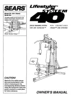
Page 1: ...ace above Serial Number Decal CAUTION Read all of the safety precau tions and Instructions in this owner s manual and in the accompanying literature before using this equipmenL Keep this owner s manua...

Page 2: ...In the stationary position with the 4 1 2 L pins except when per forming the butterfly or reverse butterfly exercise 7 The reslstanne cylinders become very hot during use Allow the resistance cylinde...

Page 3: ...ature before using the LIFESTYLER SYSTEM 40 If you have additional questions please call our Customer Service Department toll free at 1 800 999 3756 Monday through Friday 6 a m until 6 p m Mountain Ti...

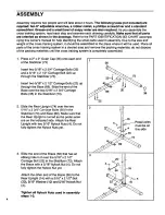
Page 4: ...Press a 2 x 2 Outer Cap 36 onto each end of the Stabilizer 73 Insert two 5 16 x 2 3 4 Carriage Bolts 35 and a 5 16 x 2 1 2 Carriage Bolt 22 up through the Stabilizer 73 Insert two 5 16 x 2 1 2 Carriag...

Page 5: ...4 Bolts 3 and 5 16 Nylock Nuts 4 Do not fully tighten the Nylock Nuts until ompletelng step 24 Press a 1 3 4 x I 3 4 Inner Cap 28 into 3 4 Round Inner Cap 30 into each side of the Arm Support Apply g...

Page 6: ...insides of the two 6 1 2 Foam Pads 84 with soapy water Slide the Foam Pads onto the Arms until the Foam Pads are 3 from the lower ends Insert the end of a Handle 52 that has a _u_ th_ou it tl Ju _ II...

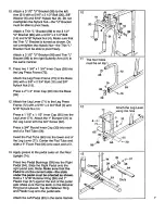
Page 7: ...x 2 3 4 Bolt 3 and 5 16 Nylock Nut 4 Press a 1 1 2 x 1 1 2 Inner Cap 95 into the Leg Lever 71 Attach the 1 Bumper 31 to the Leg Lever with the 3 4 Screw 32 Press a 3 4 Round Inner Cap 30 into each end...

Page 8: ...astic Cap onto the cylinder axle Attach a 1 Retainer Ring 47 and 5 8 Plastic Cap 46 to the right cylinder axle in the same manner 16 Raise the Right Pedal 64 and rest it on the hr _ek_t _t fh_ Inw_r _...

Page 9: ...e a Handle 52 to the right VKR Arm 57 in the same manner 20 Press a 1 1 2 x 1 1 2 Inner Cap 95 into the RARt F rAm_ R7 Attsoh the ReS P Ste _RS to the Seat Frame with the 1 4 x 2 Carriage Bolt 25 a 1...

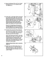
Page 10: ...Short Cable 94 is under the 2 Metal Spacer 24 Insert the other end of the Short Cable 94 86 and the Front Upright 76 Lay the Cable over a 3 1 2 Pulley 55 Hold the Pulley in the upper end of the Front...

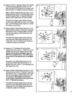
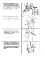
Page 11: ...the Domed Inner Cap 34 into the lower end of the Weight Selector 82 Slide a Weight 79 onto the upper end of the Weight Selector 82 Make sure that the Weight is turned so the pin groove is down ward In...

Page 12: ...nd the 3 1 3 Pulley 55 Turn the Plastic Cable Guide so it holds the Cable on the Pulley 31 Slide a Plastic Cable Guide 18 and a 3 1 2 Pulley 55 onto a 3 8 x 3 3 4 Bolt 21 Insert the Bolt into the tube...

Page 13: ...ound the 3 1 2 Pulley 55 Turn the Plastic Cable Guide so it holds the Cable on the Pulley 35 Attach a 3 U Bracket 97 to the Front Upright 76 with a 5 16 x 4 Bolt 27 5 16 Washer 10 and 5 16 Nylock Nut...

Page 14: ...e of the four holes in the Leg Press Frame 39 Find the lower ends of the two Weight Guides 83 there are holes near the upper ends of the Weight Guides Slide a Weight Bumper 50 onto the lower end of ea...

Page 15: ...Turn the Weight Sleeves so the hinged sides are toward each other 43 Tip the top Weight 79 as shown Fit the low _Ju_ Ui L _ VV_ yllL ZllLU _ VV_ lyllL _l_t_vt_ _ou Fit the high side of the Weight int...

Page 16: ...Support 85 Remove the ACTUAL RESISTANCE FOR BENCH PRESS decal from the Decal Sheet not shown Apply the decal to the left Arm 51 Remove the VERTICAL KNEE RAISE decal from the De _ _l Rhe et ncJt _hnwn...

Page 17: ...1 Remove the INDEPENDENT ACTION shown Apply the decal to the Rear Upright 74 The lower end of the decal should be aligned with the cylinder axles Remove the HOT decal from the Decal Sheet not shown Ap...

Page 18: ...e using the cross training system make sure that both of the cables are properly routed Pull the ends of both cables a few times to make sure that the cables move smoothly over the pulleys Move the bu...

Page 19: ...arm mode and TRIPLED when the leg press plate is used CHANGING THE STEPPING RESISTANCE To vary the intensity of your workouts the resis tance of the stepper pedals can be changed To change the resista...

Page 20: ...TO THE H GH C A BLE The Lat Bar 87 can be attached to the high cable with a Cable Clip 89 For some exercises the Chain 88 must be attached between the Lat Bar and the high cable with two Cable Clips T...

Page 21: ...tighten the cables hold the 5 16 x 4 Bolt 27 and turn the Nylock Nut clockwise If the cables cannot be tightened enough by turning the Nylock Nut see the instructions below Locate the two 3 1 2 Pulley...

Page 22: ...t 25 013330 1 1 4 x 2 Carriage Bolt 77 113715 1 Seat 26 013564 5 3 8 x 1 3 4 Bolt 78 113716 1 Backrest _7 Al ll _q 9 _ 1R v A _ 1 79 4na _a _ 10 _ r _ 28 113666 8 1 3 4 x 1 3 4 Inner Cap 80 109976 2 W...

Page 23: ...84 55 55 44 28 I 6 14 15_ 97 54 42 4 86 87 23 42 4 10 33 55 20 I I i I I I I 4 58 57 47 s 48 61 10 39 39 37 73 69 16 45 23...

Page 24: ...trainedtechnici ans specifically trained on SEARS products having the pads tools and equipment to ensure that we meet our pledge to you We service what we sell Should you ever need repair service or...

Reviews: