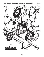
background image

10

PART LISTÑModel No. 831.288265

R0700A

Key

No.

Qty.

Description

Key

No.

Qty.

Description

Note: Ò#Ó indicates a non-illustrated part. Specifications are subject to change without notice. See the back cover
of this manual for information about ordering replacement parts.

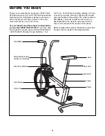
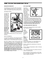
Training Zone Exercise

After warming up, increase the intensity of your 
exercise until your heart rate is in your training zone
for 20 to 30 minutes. Note: During the first few weeks
of your exercise program, do not keep your heart rate 
in your training zone for longer than 20 minutes. 

A Cool-down

Finish each workout with 5 to 10 minutes of stretching.
This will increase the flexibility of your muscles and
will help to prevent post-exercise problems.

Exercise Frequency

To maintain or improve your condition, complete three
workouts each week, with at least one day of rest
between workouts. After a few months of regular 
exercise, you may complete up to five workouts each
week if desired. 

The key to success is to make exercise a regular and
enjoyable part of your everyday life.
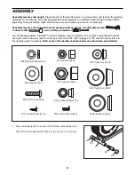
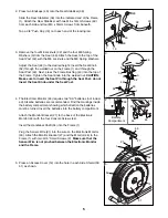
1

1

Frame

2

15

3/16" Screw

3

4

M8 Spring Washer

4

2

M8 Washer Nut

5

4

M8 Washer

6

1

Reed Switch Clamp

7

3

Flange Bushing

8

2

M6 Adjustment Nut

9

2

M6 x 51mm Adjustment Bolt

10

2

Adjustment Bracket

11

1

Fan Axle Shaft

12

1

Fan Assembly

13

1

Pedal Spacer

14

2

Access Cover

15

1

Sprocket

16

2

Pedal Shaft

17

1

Chain

18

1

Crank

19

2

3/8Ó Push Cap

20

3

M4 x 16 Tapping Screw

21

1

Reed Switch/Sensor Wire

22

1

Short Spacer

23

2

1/2" Locknut

24

2

13mm Washer

25

2

Pedal Bushing

26

2

Link Arm

27

1

Monitor Bracket

28

1

Crank Assembly

29

2

21mm Washer

30

2

Pedal

31

2

M8 Pedal Washer

32

8

M8 Locknut

33

2

Pedal Cap

34

4

Handlebar Bushing

35

2

5/8" Push Cap

36

1

Right Handlebar

37

1

Left Handlebar

38

2

Handlebar Foam

39

1

Rear Stabilizer

40

4

Endcap

41

1

Base Bumper

42

1

Seat Post

43

1

Frame Bushing

44

4

Console Screw

45

1

Long Spacer

46

1

Electronic Monitor

47

2

Link Arm Bushing

48

1

Seat

49

8

M6 x 16mm Screw

50

1

Right Side Shield

51

1

Left Side Shield

52

1

Seat Knob

53

1

Sensor Magnet

54

1

5/8Ó Handlebar Shaft

55

2

Pedal Spring

56

2

17.5mm Washer

57

4

Handlebar Endcap

58

2

M10 Flat Washer

59

2

M8 Hex Nut

60

3

M4 x 25mm Tapping Screw

61

1

Fan Plate

62

1

Fan Sprocket

63

1

Seat Post Bushing

64

2

21mm Flat Washer

65

2

Frame Extension

66

1

M6 x 9mm Screw

#

1

Grease Pack

#

1

User's Manual

Summary of Contents for 831.288263

Page 1: ...and instruc tions in this manual before using this equipment Keep this manual for future reference Model No 831 288265 Serial No _ Write the serial number in the space above for future reference Serial Number Decal SEARS ROEBUCK AND CO HOFFMAN ESTATES IL 60179 ...

Page 2: ...ways wear athletic shoes for foot protection 9 When adjusting the seat insert the seat knob through the welded nut on the frame and through the seat post Do not insert the seat knob under the seat post Tighten the seat knob into the welded nut 10 Always sit on the seat when using the DT1000 never stand up on the pedals 11 If you feel faint dizzy or short of breath stop immediately and begin coolin...

Page 3: ...enefit read this manual carefully before you use the LIFESTYLER DT1000 If you have addi tional questions please call our toll free HELPLINE at 1 800 736 6879 Monday through Saturday 7 a m until 7 p m Central Time excluding holidays To help us assist you please note the product model number and serial number before calling The model number is 831 288265 The serial number can be found on a decal att...

Page 4: ... drawings below to identify the small hardware used in assembly The number in parenthesis beneath each part refers to the key number of the part from the PART LIST on page 10 The second number refers to the quantity used in assembly Note some of the hardware shown below may have been pre attached ASSEMBLY 3 8 Push Cap 19 2 1 2 Locknut 23 2 M8 Locknut 32 8 Link Arm Bushing 47 2 Pedal Bushing 25 2 3...

Page 5: ...p of the Frame Tighten the Seat Knob into the welded nut CAUTION Make sure to insert the Seat Pin through the Seat Post do not insert the Seat Knob under the Seat Post 4 The Electronic Monitor 46 requires two AA batteries not includ ed Alkaline batteries are recommended Find the markings inside the battery compartment showing which direction the batteries must be turned Insert the batteries into t...

Page 6: ...en the 1 2Ó Locknut 23 back onto the Pedal Shaft Make sure that the 17 5mm Washer 56 can be moved back and forth on the shoulder of the Pedal Shaft Fit the end of the right Link Arm 26 onto the Pedal Shaft and slide the Link Arm onto the Pedal Bushing 25 Attach the other pedal assembly to the left arm of the Crank not shown in the same manner 7 8 6 Lubricate the Handlebar Shaft 54 Slide the Right ...

Page 7: ... the Pedal Bushings If the Link Arms are not on the Pedal Bushings the Link Arms may slip off during use resulting in injury to the user SEAT ADJUSTMENT Proper seat height is impor tant for effective exercise As you pedal there should be a slight bend in your knees when the pedals are in the lowest posi tion To adjust the Seat 48 dismount the exercise cycle hold the Seat and remove the Seat Knob 5...

Page 8: ...lems are the result of drained batteries See assembly step 4 on page 5 for battery installation instructions If the electronic monitor still does not function properly the sensor wire should be checked See assembly step 4 on page 5 Slide the electronic monitor off the frame and make sure that the sensor wire is plugged fully into the wire on the electronic monitor TIGHTENING THE PEDALS If the peda...

Page 9: ...ise For maximum fat burning adjust your pace until your heart rate is near the middle number in your training zone as you exercise Aerobic Exercise If your goal is to strengthen your cardiovascular system your exercise must be Òaerobic Ó Aerobic exercise is activity that requires large amounts of oxygen for prolonged periods of time This increases the demand on the heart to pump blood to the muscl...

Page 10: ...rew 3 4 M8 Spring Washer 4 2 M8 Washer Nut 5 4 M8 Washer 6 1 Reed Switch Clamp 7 3 Flange Bushing 8 2 M6 Adjustment Nut 9 2 M6 x 51mm Adjustment Bolt 10 2 Adjustment Bracket 11 1 Fan Axle Shaft 12 1 Fan Assembly 13 1 Pedal Spacer 14 2 Access Cover 15 1 Sprocket 16 2 Pedal Shaft 17 1 Chain 18 1 Crank 19 2 3 8Ó Push Cap 20 3 M4 x 16 Tapping Screw 21 1 Reed Switch Sensor Wire 22 1 Short Spacer 23 2 1...

Page 11: ...19 15 17 53 18 28 40 39 40 49 43 23 52 13 20 2 35 42 32 48 57 37 32 34 50 38 2 2 54 9 4 10 8 27 62 44 58 45 64 59 60 61 7 58 22 59 64 11 12 40 40 26 32 5 46 35 30 36 38 57 1 14 21 49 49 57 63 28 57 3 3 20 41 20 32 65 65 66 EXPLODED DRAWINGÑModel No 831 288265 R0700A 11 ...

Page 12: ...No 831 288265 QUESTIONS If you find that you need help assembling or operating the LIFESTYLER DT1000 a part is missing or you need to schedule repair service call our toll free HELPLINE 1 800 736 6879 MondayÐSaturday 7 amÐ7 pm Central Time excluding holidays REPLACEMENT PARTS If parts become worn and need to be replaced call the following toll free number 1 800 FON PART 1 800 366 7278 FULL 90 DAY ...

Reviews: