background image

Downloaded from 

www.Manualslib.com


manuals search engine


Summary of Contents for Craftsman 113.225900

Page 1: ...d serial number may be found at the right hand side of the base You should record both model and serial number in a safe place for CAUTION Read SAFETY INSTRUCTIONS carefully BEL T AND D SC SANDER asse...

Page 2: ...etc 17 AVOID ACCIDENTAL STARTING Make sure swdch s m OFF position before pluggmg Ln 18 USE RECOMMENDED ACCESSORIES Don t LISP Dower tOOlS in damp or wet locations or ex Consult tbeowner s manua for re...

Page 3: ...ht stand on the tool to reach them BEFORE EACH USE Inspect your sanderl DISCONNECTTHE SANDER To avoid injury from accidental starting unplug the sander turn the switch off and remove the switch key be...

Page 4: ...d footing and balance Keep your face and booy to one side out of line with a pos sible throwback WHENEVER SANDER IS RUNNING WARNING Don t let familiarity gained from frequent use of your belt and disc...

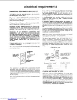
Page 5: ...utlet box A temporary adapter as illustrated is available for connecting plugs to 2 prong receptacles The temporary adapter should be used only until a properly grounded outlet can be installed by a q...

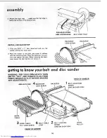
Page 6: ...R PARTS 25 Motor Connections 29 unpacking and checking Model 113 225900 Belt and Disc Sander is shipped complete in one carton but DOES NOT INCLUDE Steel Legs or Motor Model 113 225931 Belt and 0isc S...

Page 7: ...l t P 9 Abrasive Disc 1 Q Sanding Disc w Set Screw 1 R Belt Sanding 1 Bag Assembly Outlet Part No 68064 Containing the following loose parts S Outlet on off Power 1 T Switch Key 1 U Bracket Switch Mou...

Page 8: ...ORT _ k _ LEG SCREW CHANNEL SUPPORT MOTOR SUPPORT NUT LOCKWASHER LEG SCREW WHEN INSTALLING OR MOVING THE SANDER AVOID DANGEROUS ENVIRONMENT Use the sander n a dry indoor place protected from rain Keen...

Page 9: ...ve the protective coating that is applied at the factory from the belt table Use any ordinary house hold type grease and spot remover WARNING Never use gasoline naptha or similar highly volatile solve...

Page 10: ...There is a flat spot on the shaft near the end Rotate the shaft so that the flat spot is facing up 11 Place the disc on the shaft so that the set screw ts facmc up Position the disc so that it is app...

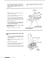
Page 11: ...ked X in motor mounting bracket DO NOT TIGHTEN BOLTS AT THIS TIME The L bracket which holds the guard support must be slid between the motor base and the motor mounting bracket so motor must be loosel...

Page 12: ...tension to belt and tighten motor bolt nuts 9 Check guard support before tightening guard support screws Guard support must becentered around motor shaft Tighten screws 10 Push guard into position on...

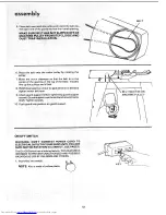
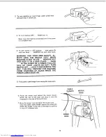
Page 13: ...WER FAILURE ALL OF YOUR LIGHTS GO OUT TURN SWITCH OFF LOCK ITAND REMOVE THE KEY THIS WILL PREVENT THE MACHINE FROM STARTING UP AGAIN WHEN THE POWER COMES BACK ON 5 Find plastic cable hanger from among...

Page 14: ...the smooth side of the abrasive belt you will find a DIRECTIONAL ARROW dl r n ectlonal arrow The abras ve belt must run _ in the direction of this arrow so that the splice does not come apart 1 Loosen...

Page 15: ...s moving while pulling the wrench toward you This will move the abrasive belt to the left PUSHING the wrench will move the belt to the right d The abrasive belt is tracking properly when it is centere...

Page 16: ...o pos tion and tighten the bolt When removing the bacK stop loosen the bolt but do not remove it BACKSTOP BACKSTOP LOCK SCREW getting to know your belt and WARNING FOR YOUR OWN SAFETY TURN SWITCH OFF...

Page 17: ...ONE ON EACH SIDE 3 WORK TABLE TILT LOCK SCREW locks the table It is locked using the 1 2 wrencn a Using a combination square check the angle of the table with the disc NOTE The ombination square must...

Page 18: ...epositioned on the rod to maintain a maxtmum 1 16 inch space between the table and sanding surface STOP SCREW 4 BACKSTOP LOCK SCREW locks the backstop in place It is locked u_ing the 1 2 wrench BACKST...

Page 19: ...ch is OFF before plugging sander into a power outlet Plan your work USE THE RIGHTTOOL Don t force tool or attachment to do a job it was not designed to do CAUTION This machine is not designed for heav...

Page 20: ...g Before freeing any jammed material Turn switch OFF Unplug the sanaer Wait for all mov ng parts to stop fo avoid throwback of the workpiece use workpiece supports for all flat surface sanding BEFORE...

Page 21: ...a miter gauge_ NOTE Use a combination square to square the miter gauge to the face of the disc If it is not squat e pull out the index pin loosen the miter gauge knob and move the miter gauge slightly...

Page 22: ...gine oil SAE 20 3 If disassembl_ of ne motor is necessary it should be returned to your nearest Sears retad or mall order store n order to prevent vo dtng the guarantee NOTE The s _eea of thts motor c...

Page 23: ...1 Abrasive disc or belt is glazed with sap 1 2 3 REMEDY Replace defective pa_ts before 4sing b l_ dsc sai_ ler agai_ Reset p_otector after motor has cooled Coqsuit S_ a s S_ TvI e Ally attemt t _o lep...

Page 24: ...ken connections Starting switch not operating Voltage too low to permit motor to reach operating speed 3 Fuses or circuit breakers do not have sufficient capacity 1 Motor overloaded 2 Fuses or circuit...

Page 25: ...d 1 4 20 x 5 8 t Nut Hex1 4 20 1 Lockwasher 1 4 External Channel Support Stiffener Side Stiffener End Support Motor 1 Nut Hex1 2 13 1 Foot Leveling 1 Bagof LooseParts Not illustrated STD523125 STD5511...

Page 26: ...3 225900 113 225931 22 g _ 24 21 25 26 17 23 l 23 i t9 15 4_ 30 19 28 14 i_q 8 9 _0 I1 28_ 58 65 64 57 63 62 45 46 47 48 49 44 46 47 68 61 59 6O 66 39 4O 38 37 67 10 Q me Q ql FIGURE 2 Downloaded from...

Page 27: ...6 32 x 7 16 Cam Left Hand Spr ir_g Cam Bight Hand Guard Idler Screw Machine Pan Head No 8 32 x 3z8 M_y Be P_cha _J L ocallv I Stock Item Key No 36 37 38 39 40 41 42 43 44 45 46 47 48 49 50 51 52 53 5...

Page 28: ...IFIED SERVtCE TECHNICIAN REPAIR SERVICE IS AVAILABLE AT YOUR NEAREST SEARS STORE 3 FIGURE 3 MOTOR PART NO 68072 SUPPLIED WITH MODEL 113 225931 ONLY Key Part jl No No I Description I 60306 Screw 8 32 x...

Page 29: ...d motor frame See illus 3 Reinsert GREEN SCREW in the threadedhote Tighten securely 4 Insert terminal end of WHITE wire on spade terminal marked T4 on the motor Push terminal firmly until seated 5 Ins...

Page 30: ...x 3 4 Bracket Switch Mounting Screw Pan Hd Plastite No 8 x 3 8 Standard Hardware item May be Purchased Locally Does Not Include Key No 3 Order Separately If Required TStock Item May be secured through...

Page 31: ...NOTES 31 Downloaded from www Manualslib com manuals search engine...

Page 32: ...Sander will be found on a plate attached to your sander at the right hand side of the base WHEN ORDERING REPAIR PARTS ALWAYS GIVE THE FOLLOWING INFORMATION PART NUMBER MODEL NUMBER 113 225900 OR 113 2...

Reviews: