background image

Summary of Contents for Craftsman 917.254920

Page 1: ...OWNER S MANUAL MODEL NO 917 254920 Caution Read and follow all Safety Rules and Instructions Before Operating This Equipment Sears Roebuck and Co Chicago IL 60684 U S A l ...

Page 2: ...c high ways 20 Exercise special care when mowing around fixed objects in order to prevent the blades from striking them Never delib erately run tractor or mower into or over any foreign objects 21 Never shift gears until tractor comes to a stop 22 Never place hands or feet under the mower in discharge chute or near any moving parts while tractor or mower Is running Always keep clear of discharge c...

Page 3: ...ing equipment is maintained lubricated and tuned up according to the operating and maintenance instruction in the owner s manual Sears will repair free of charge any delect in material or workmanship in this electric start riding equipment This warranty excludes b_ade s blade adapter s spark p ug s air cteaner and belt s which are expendable and become worn during normal use This warranty does not...

Page 4: ... Filter _ 18 Lubrication Chart 24 Spark Plugs t 18 Tire Care _ 7 14 Mower Adjustment Front to Bier 23 Adjustment Side to _ide I 22 Blade Sharpening _ 14 Blade Replacem_ht t 14 Cutting Level _ _ 12 22 Operatio 11 Ben ova _21 Mowing Tips _ 12 Muffler 17 Spark Arrester 2 O Oil Cold Weather Conditions 16 Engine 16 Storage 23 Operation 9 12 Operating Your Mower 11 Operating Your Tractor 11 Starting the...

Page 5: ...ize ___ fill lltlltltl iltlltlfilll lllllllltlltlll Ill l 2 Battery Carriage Bolts 1 4 x 20 x 7 1 2 Terminal Guard t5 Slope Instruction 2 Keys Steering Wheel Adapter Steering Wheel Insed NOTE RIGHT HAND R H AND LEFT HAND L H ARE DETERMINED FROM OPERATOR S POSITION WHILE SEATED ON THE TRACTOR The operation of any tractor can result in foreign objects thrown into the eyes which can result in severe ...

Page 6: ... STEERING WHEEL _IIIIHIII_ 2 Hex Bolt 1 4 20 x 3 4 2 Wing Nut 1 4 20 2 Washer 9 32 x 5 8 x 16 Ga 2 Lock Washer 1 4 2 Hex Nut 1 4 20 F IIlliI _LJ t Adjustment Bot 1 Lock Washer t 2 I _ T Tm I1 1 Washer 17 32 x _ 1 3 16 x 12 Gao 1 _ r 1 Locknut 1 2 20 1 Shoulder Bolt 5 16 18 2 Sheet Metal Screw 10 16 x 1 2 ABTBS ___ t Washer 2 1 4 6 ...

Page 7: ...tainer Stir with a wooden or plastic paddle while adding baking soda until the addition of more soda causes no more foaming fo It is recommended that the battery be charged be fore use Use a 12 volt battery charger Charge bat ten at a rate of 6 amperes for 1 hour NOTE OB SERVE SAFETY PRECAUTIONS LISTED IN BOX ABOVE REQUIRED FOR BATTERY CHARGING Check the acid level after the battery is charged If ...

Page 8: ...T DOORS BATTERY _ _ _KEY DRAIN TUBE HOLE d eo f 8 Place 2 1 4 diameterwasheron steering shaft and install a I 2 locknut washer and Iocknut found in bag of parts Tighten securely 9o Snap insert into steering wheel Remove plastic on tractor hood Raise attachment lift handle see page 9 Roll Tractor off skid Be careful of staples in skid 4 Check Tires Check the air pressure in the tires Tires with too...

Page 9: ...TCH ADJUST MENT SLOTS CONTROL CLUTCH BRAKE PEDAL MOWER DECK HEIGHT ISTMENT POSITIONING PARKING BRAKE GEARSHIFT LEVER KNOW YOUR ATTACHMENTCLUTCH LEVER Push lever upto engage attachment There will be an engine hesitation as the clutch engages ATTACHMENT LIFT LEVER Use the attachment litt lever to raise and lower the attachment mounted to your tractor Pull lever back slightly and push button then mov...

Page 10: ...h might be damaging to ATTACHMENT CLUTCH LEVi_R yo_r engine ENGAGED POSITION b Fil fue tank Fig 6 Use fresh clean regular un leaded gasoline Capacity is 5 quarts 4 7 titres DISENGAGED_ POSITION NOTE FRESH CLEAN WINTER GRADE FUEL MUST BE USED TO INSURE GOOD COLD WEATHER STARTING SWITCH THROTTLE CONTROL PARKING BRAKE POSITION GEARSHIFT LEVER FILL TO BOTTOM OF GAS TANK FILLER NECK DO NOT OVERRLL WIPE...

Page 11: ... and function of all controls 3 Keep guards safety shield and switches in place and working 4 Remove objects that can be thrown by blades 5 Do not mow when children and others are around 6 Never carry children or passengers 7 Always look behind machine before backing 8o Do not mow where machine can tip or slip 9o tf machine stops going uphill stop blades and back slowly down 10 Be sure blades and ...

Page 12: ... and more uniform cutting d When mowing large areas Fig 9 start by turning to tile rightso that the clippings will discharge away from shrubs fences driveways etc After two or three rounds mow in the opposite direction making left hand turns until finished e _ If grass is extremely tall it should be mowed twice The first time cut relatively high the second time to the desired heighL fo The left ha...

Page 13: ...PLETELY STOPPED 7 REMOVE IGNITION KEY 8 DISCONNECTTHE SPARK PLUG WIRE FROM THE SPARK PLUG AND KEEP WIRE AWAY FROM THE SPARK PLUG TO PREVENT INJ URY FROM ACCIDEN TAL STARTING BE CAREFUL TO AVOID TOUCHING HOT ENGINE OR MUFFLER COMPONENTS SERVICE RECORD FILL IN DATES AS YOU COMPLETE REGULAR SERVICE Check Engine Oil Level Change Engine Oil Check Brake Operation Check Tire Pressure Sharpen Mower Blades...

Page 14: ...ep ruts sharp objects and other hazards that may cause tire damage d Removing wheel for tire repair Fig 12 1_ Block up axle securely 2 Remove hub cap klip ring and washer to allow wheel removal rear wheel contains a square key Do Not Lose 3 Repair tire and reassemble Atign slots in rear wheel hub and axle Insert square key_ Re place washers and snap klip ring securely in axle groove Replace hub ca...

Page 15: ... Corrosion and dirt on the battery and terminals cause the battery to leak power and hinders the operation of the charger LEAD ACID BATTERIES GENERATE EXPLOSIVE GASES KEEP SPARKS FLAME AND SMOKING MATERIALS AWAY FROM BATTERIES ALWAYS WEAR EYE PROTECTION WHEN AROUND BATTERIES a b Remove terminal guard Disconnect BLACK battery cable then RED battery cable and remove battery from tractor co Wash batt...

Page 16: ...ace If very dirty replace cartridge Reassemble air cleaner NUTS HOLDING AIR CLEANER CARTRIDGE MUST BE INSTALLED WITH FIBER WASHERS DOWN ON CARTRIDGE PLATE TO PREVENT DIRT FROM ENTERING CARBURETOR TJGHTEN NUTS BY HAND OVER TIGHTENING COULD COLLAPSE CARTRIDGE NOTE NEVER RUN ENGINE WITH AIR CLEANER RE MOVED_ 8 Clean Air Screen and Engine Cooling Fins FIGURE t6 IMPORTANT TO AVOID DAMAGE TO THE STARTIN...

Page 17: ...l of fully charged battery c Connect the other end of the BLACK jumper cable to the L H side panel bolt Fig 19 NOTE KEEP AWAY FROM GAS TANK AND BATTERY d Disconnect cables in reverse order 1 L Ho side panel bolt Fig 19 2 Negative terminal of fully charged battery 3 Positive terminals REPAIR AND ADJUSTMENT BOLTS SCREWS STARTER HOUSING BLOWER HOUSING J AIR SCREEN BOLTS STARTER POSITIVE WASHER WASHER...

Page 18: ... turn eo With throttle control lever in SLOW position turn idle mixture screw counterclockwise t _ until en gine runs rough and then turn clockwise _ until engine begins to die Turn idle mixture screw to a point midway between these positions L With throttle control lever in SLOW position en gine should idle at 1750 RPM If engine idles too slow push throttle control lever above idle and turn idle ...

Page 19: ...ing brake Pull belt as far as possible over top of clutch pulley g Reset parking brake Pull belt over top of clutch pul ley Fig 23 h Pull belt out through shift gate to remove from trac tor Fig 24 io Install belt by reversing above procedure REPLACE BELTONLY WITH THE BELT LISTED IN THE REPAIR PARTS SEC TION OF THIS MANUAL 17 Fuse Replacement Replace with 30 amp automotive type plug in fuse The fus...

Page 20: ...o WEAR SAFETY GOGGLES DURING REMOVAL AND INSTALLATION d_ Lower hood half way and grasp atthe bottom of the grill and at the upper hoodedge Fig 26 Lift hood up out and away from tractor e_ Place hood carefully on the ground 19 Hood installation a Pick hood up at top of grill and upper hood edge Fig 27 b_ Align hood pivot rod with hinge brackets Rotate hood half way down slide pivot rod in and down ...

Page 21: ...through axle and parallel link Fig 32 Secure with retainer spring c Install rear hinge pin through mower lift brackets and parallel link Fig 32 Secure with retainer spring do Install clutch rod in clutch lever Fig 32 e Move attachment lift lever Figo30 forward to lower suspension arms Slide trunnions through lift bracket holes and secure with retainer springs Fig 29 f Roll belt over engine pulley ...

Page 22: ...or has been manufactured with the ability to read just the mower belt drive to provide you with longer belt life If the attachment clutch lever travels 4 1 2 11 43 cm up the slot in the dash before spring resistance is evident ad justment is necessary NOTE CHECK FOR PROPER SPRING TENSION WITH THE ENGINE OFF AND THE LIFT LEVER IN THE HIGHEST POSITION a Lower the mower deck for easier access b Using...

Page 23: ...ean dry area A Fuel System It is important to prevent gum deposits from forming in es sential fuel system parts such as the carburetor fuel filtffi fuel hose or tank during storage Also experience indicates that alcohol blended fuels called gasohol or using ethaDol or methanol can attract moisture which leads to separation and formation of acids during slorage Acidic gas ca _ dam age the fuel syst...

Page 24: ...AND ADJUSTMENT LUBRICATION CHART Q FRONT WHEEL _ BEARING Q ENGINE MOWER CLUTCH PIVOT Q I t FRONT WHEEL Q BEARING Q SAE 30 MOTOR OIL Q GENERAL PURPOSE GREASE Q REFER TO PAGE 16 FOR ENGINE OIL SPECIFICATIONS 24 ...

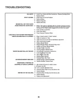
Page 25: ...eplace Starter or Solenoid Charge or Replace Battery Check Wire Connections and Ground Points Place Throttle Control in FAST position and run starter several times to clear out gas w Remove Air Filter and clean Replace Spark PIug s and adjust gap _ Rechargeor replace Battery _r Check the Wiring w Drain Fuel Tank and Carburetor Use Fresh Fuel Replace Fuet Filter 8 Make necessary adjustments to Carb...

Page 26: ...pressure in Tires _ Ch_ck front to _rear and sUe to side Mower adjustment Us_ea slower around speed Re_lace Mower Blades _ Re_stall Morner Blades with Sharp Edge down _ Repr_ce wll i_roper Mower Blades Readiust M Drive Be _r Clean _nd_ _e of Mower Deck MOWER BLADES WILL NOT ROTATE _ Correct Clu h mechanism interference _ InstaII ndw 4ower Drive Belt _ Adjust Mo_ _er Drive Belt Replace lfi _en Mand...

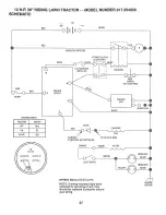
Page 27: ... 7 _ _ WHtTE u CLUTCH BRAKE _ J SOLENOID PETALUP __ I SEAT SWITCH NOTOCCUPIED __ BLACK IGNITION UNIT SPARKPLUG DIODE RED _ __ CHARGING COIL 3 AMP_DC 20 VOLTSAC MIN AT3_00 RPM BATTERY N LINE ORANGE LIGHT SWITCH _H_TE ACCOIL j_j _jk j BROWN HEADLIGHT BLACK HEADLIGHT BLACK WIRING INSULATED CLIPS NOTE If wiring insulated clips were removed for servicing of unit they should be replaced to properly secu...

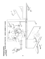
Page 28: ... _ O_ E 01 iii m 3 Z LU 3 0 I 0 t Z _z u _a _J LU_ W J Lu o L_ 28 ...

Page 29: ...PAGES 29 48 REFER TO SEPARATE REPAIR PARTS DOCUMENT ...

Reviews: