background image

16

ENGINE

Maintenance, repair, or replacement of the emission con-
trol devices and sys tems, which are being done at the 
cus tom ers ex pense, may be performed by any non-road 
engine repair es tab lish ment or in di vid u al.  Warranty repairs 
must be per formed by an authorized engine man u fac tur er's 
service outlet.

SERVICE  AND ADJUSTMENTS

FIG. 28

CABLE CLIP
SCREW

DRIVE
CONTROL
CABLE

EXTENSION
SPRING

ENGINE
PULLEY

IDLER
PULLEY

TRANS MIS SION 
PULLEY

LESS 
TEN SION

5/8"

MORE
TEN SION

TO REPLACE GROUND DRIVE BELT    
(See Figs. 23 and 28)

•      Remove belt guard (See “TO REMOVE BELT GUARD” 

in this section of this manual).

•      Remove old belt by slipping off engine pulley fi rst then 

remove from transmission pulley.

•     Place new  belt in groove of transmission pulley and 

into engine pulley.  BELT MUST BE IN GROOVE ON 
TOP OF IDLER PULLEY.  NOTE POSITION OF BELT 
TO GUIDES.

•      Check belt adjustment as described below.
•      Replace belt guard.
•     Reposition wheel and replace clevis pin and hairpin 

clip.

•      Replace inner and outer side shields.

GROUND DRIVE BELT ADJUSTMENT  
(See Fig. 28)

For proper belt tension, the extension spring should 
have about 5/8 inch stretch when drive control bar is in 
“EN GAGED” position.  This tension can be attained as 
follows:
•     Loosen cable clip screw securing the drive control 

cable.

•     Slide cable forward for less tension and rearward for 

more tension until about 5/8 inch stretch is obtained 
while the drive control bar is engaged.

•      Tighten cable clip screw securely.

TO ADJUST CARBURETOR

The carburetor has been preset at the fac to ry and ad just ment 
should not be nec es sary.  However, engine per for mance 
can be affected by dif fer enc es in fuel, tem per a ture, al ti tude 
or load.  If the carburetor does need ad just ment, contact 
your nearest Sears or other qualifi ed service center.

IMPORTANT:

  NEVER TAMPER WITH THE EN 

GINE 

GOVERNOR, WHICH IS FACTORY SET FOR PROP 

ER 

ENGINE SPEED.  OVER SPEED ING THE ENGINE ABOVE THE 
FACTORY HIGH SPEED SET TING CAN BE DANGEROUS.  IF 
YOU THINK THE EN GINE-GOVERNED HIGH SPEED NEEDS 
AD JUST ING, CONTACT YOUR NEAREST SEARS OR OTHER 
QUALIFIED SERVICE CENTER WHICH HAS THE PROPER 
EQUIP MENT AND EX PE RI ENCE TO MAKE ANY NEC ES SARY 
AD JUST MENTS.

Summary of Contents for CRAFTSMAN 944.625930

Page 1: ...uctions Before Operating This Equipment MODEL NO 944 625930 OWNER S MANUAL Assembly Operation Maintenance Service and Adjustments Repair Parts 5 0 HP 17 INCH TINE WIDTH REAR TINE TILLER WITH COUNTER ROTATING TINES Sears Canada Inc Toronto Ontario M5B 2B8 ...

Page 2: ... the controls and the proper use of the equipment Know how to stop the unit and disengage the controls quickly Never allow children to operate the equipment Never allow adults to operate the equipment without proper instruction Keep the area of operation clear of all persons par ticularly small children and pets PREPARATION Thoroughly inspect the area where the equipment is to be used and remove a...

Page 3: ...ECTION OF THIS MANUAL FOR PART NUMBER SAFETY RULES 2 CUSTOMER RESPONSIBILITIES 3 PRODUCT SPECIFICATIONS 3 WARRANTY 3 ASSEMBLY 4 6 OPERATION 7 11 MAINTENANCE SCHEDULE 12 TABLE OF CONTENTS MAINTENANCE SCHEDULE 12 13 SERVICE ADJUSTMENTS 14 16 STORAGE 17 TROUBLESHOOTING 18 REPAIR PARTS TILLER 19 25 REPAIR PARTS ENGINE 26 30 SERVICE PARTS ORDERING BACK COVER LIMITED TWO 2 YEAR WARRANTY ON CRAFTSMAN TIL...

Page 4: ...ating position standing behind tiller handles Your new tiller has been assembled at the factory with exception of those parts left unassembled for shipping purposes To ensure safe and proper operation of your tiller all parts and hardware you assemble must be tightened securely Use the correct tools as necessary to insure proper tightness 1 Carriage Bolt 3 8 16 UNC x 1 Gr 5 1 Center Locknut 3 8 16...

Page 5: ...DLE LOCK HANDLE ASSEMBLY UP POSITION FIG 4 UNPACKING CARTON See Fig 2 CAUTION Becarefulofexposedstaples when handling or disposing of carton ing material IMPORTANT WHEN UNPACKING AND ASSEMBLING TILLER BE CAREFUL NOT TO STRETCH OR KINK CABLES While holding handle assembly cut cable ties securing handle assembly to top frame Let handle assembly rest on tiller Remove top frame of carton Slowly ease h...

Page 6: ...LLER FROM CRATE Adjust handle assemby to lowest position Be sure lock lever is tightened securely Makesureshiftleverindicatorisin N neutral position See Fig 7 Tilt tiller forward by lifting handle Separate cardboard cover from leveling shield Rotate tiller handle to the right and pull tiller out of carton CHECK TIRE PRESSURE The tires on your unit were overinflated at the factory for shipping purp...

Page 7: ...ls may appear on your Tiller or in literature supplied with the product Learn and understand their meaning SHIFT LEVER DEPTH STAKE LEVELING SHIELD OUTER SIDE SHIELD DRIVE CONTROL BAR DEPTH STAKE Controls depth at which tiller will dig DRIVE CONTROL BAR Used to engage tines LEVELING SHIELD Levels tilled soil OUTER SIDE SHIELD Adjustable to protect small plants from being buried RECOIL STARTER HANDL...

Page 8: ...CTLY BEHIND TILLER Release the drive control bar Move throttle control to SLOW position Move shift lever indicator to R reverse position Hold drive control bar against the handle to start tiller movement HARD TO SHIFT GEARS Brieflyengagedrivecontrolbarandreleaseorrocktiller forward and backward until are able to shift gears FIG 9 DRIVE CONTROL BAR DISENGAGED POSITION TRANSPORT POSITION DEEPEST TIL...

Page 9: ...uel in quantities that can be used within 30 days to assure fuel freshness CAUTION Fill to within 1 2 inch of top offueltanktopreventspillsandtoallow for fuel expansion If gasoline is ac cidentally spilled move machine away from area of spill Avoid creating any source of ignition until gasoline vapors have disappeared Wipe off any spilled oil or fuel Do not store spill or use gasoline near an open...

Page 10: ... secured to the tine shaft with shear pins See TINE REPLACEMENT in the Service and Adjustments section of this manual If the tiller is unusually overloaded or jammed the shear pins are designed to break before internal damage occurs to the transmission If shear pin s break replace only with those shown in the Repair Parts section of this manual TO START ENGINE See Fig 13 CAUTION Keep drive control...

Page 11: ...o further growth of weeds and grass See Fig 15 FIG 15 OPERATION tire_1 HAIRPIN CLIP FIG 16 OUTER VIEW OF TIRE tire_2 FIG 17 INNER VIEW OF TIRE CLEVIS PIN HAIRPIN CLIP ADJUST WHEELS FOR CULTIVATING See Figs 16 and 17 Place blocks under right hand side of tiller and remove hairpin clip and clevis pin from right hand wheel Move wheel outward approximately 1 inch until hole in inner wheel hub lines up...

Page 12: ...ooperatorabuseornegligence Toreceive fullvaluefromthewarranty theoperatormustmaintaintiller as instructed in this manual Some adjustments will need to be made periodically to properly maintain your tiller All adjustments in the Service and Adjustments section of this manual should be checked at least once each season Once a year you should replace the spark plug clean or replace air filter and che...

Page 13: ...rom running low on oil Changetheoilafterevery25hoursofoperationoratleastonce a year if the tiller is not used for 25 hours in one year Check the crankcase oil level before starting the engine and after each five 5 hours of continuous use Add SAE 30 motor oil or equivalent Tighten oil filler plug securely each time you check the oil level AIR FILTER See Fig 20 Your engine will not run properly and ...

Page 14: ... tires un lessbeadsareseated overinflationcan cause an explosion Maintain 20 pounds of tire pressure If tire pressures are not equal tiller will pull to one side Keep tires free of gasoline or oil which can damage rubber TO REMOVE WHEEL See Fig 22 Place blocks under transmission to keep tiller from tipping Remove hairpin clip and clevis pin from wheel Remove wheel and tire Repair tire and reassemb...

Page 15: ...d tine edges will rotate rearward from above TINE 3 1 2 MAX TINE FIG 24 TINE REPLACEMENT See Figs 24 25 and 26 CAUTION Tines are sharp Wear gloves or other protection when han dling tines A badly worn tine causes your tiller to work harder and dig more shallow Most important worn tines cannot chop and shred organic matter as effectively nor bury it as deeply as good tines A tine this worn needs to...

Page 16: ...ce inner and outer side shields GROUND DRIVE BELT ADJUSTMENT See Fig 28 For proper belt tension the extension spring should have about 5 8 inch stretch when drive control bar is in ENGAGED position This tension can be attained as follows Loosen cable clip screw securing the drive control cable Slide cable forward for less tension and rearward for more tension until about 5 8 inch stretch is obtain...

Page 17: ... Inspect and replace belts if necessary See belt re placement instructions in the Service and Adjustments section of this manual Lubricate as shown in the Maintenance section of this manual Be sure that all nuts bolts and screws are securely fastened Inspect moving parts for damage breakage and wear Replace if necessary Touch up all rusted or chipped paint surfaces sand lightly before painting ENG...

Page 18: ...fuel 6 Drain fuel tank and refill with fresh gasoline 7 Water in fuel 7 Drain fuel tank and carburetor and refill tank with fresh gasoline 8 Clogged fuel tank 8 Remove fuel tank and clean 9 Spark plug wire loose 9 Connect and tighten spark plug wire 10 Dirty engine air screen 10 Clean engine air screen 11 Dirty clogged muffler 11 Clean replace muffler 12 Carburetor out of adjustment 12 Make necess...

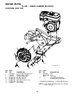
Page 19: ... Flange 26 110675X Clutch Cable 27 73900400 Nut Lock 1 4 20 31 150696 Bolt Pivot 2 141406 Grip Handle 3 110673X Grommet Handle 4 127254X Bar Drive Control Assembly 5 6712J Cap Vinyl 6 189347X010 Panel Control 7 110641X Bushing Split 9 72010520 Bolt 5 16 18 unc x 2 1 2 10 110646X Handle Grip 11 STD624003 Retainer Spring 12 81328 Bolt Shoulder 13 187497 Handle Shift 14 109313X Grommet Rubber 15 1107...

Page 20: ...1312 Washer 13 32 x 13 16 x 12 Ga NOTE All component dimensions given in U S inches 1 inch 25 4 mm 1 STD541431 Nut Keps 5 16 18 2 STD551137 Washer Lock 3 8 3 STD541037 Nut Hex 3 8 16 4 170127 Shield Inner Belt Guard 5 164329 Pin Spirol Flared 6 110111X Lever Shift 7 STD532505 Bolt Carriage 1 4 20 x 1 2 Gr 5 8 8700J Plate Shift Indicator 9 86777 Screw Hex Washer Head Slotted 10 24 x 1 2 10 9484R Cl...

Page 21: ...16 18 5 102332X Bracket Reinforcement 7 102173X Counter Weight R H 8 STD551137 Washer Lock 3 8 9 STD541037 Nut Hex 3 8 16 10 STD523715 Bolt Hex 5 16 18 x 1 1 2 11 STD624003 Clip Hairpin 12 126875X Rivet Drilled 13 102190X Tire 183122X624 Rim 795R Tire Valve 15 Engine See breakdown Honda Model GC160QHA2 STANDARD HARDWARE PURCHASE LOCALLY NOTE All component dimensions given in U S inches 1 inch 25 4...

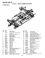
Page 22: ...1 2 52 STD541031 Nut Hex 5 16 18 53 165140 Kit Bearing 58 179520 Bolt Shoulder 60 183226 Fitting Grease 6066J Grease Plastilube 1 NOTE All component dimensions given in U S inches 1 inch 25 4 mm KEY PART NO NO DESCRIPTION 1 188554 Transmission Assembly Includes Key Nos 2 52 2 188482 Gearcase L H w Bearing In cludes Key No 4 3 161963 Gasket Gearcase 4 5020J Bearing Needle 5 1370H Washer Thrust 5 8 ...

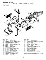
Page 23: ...x 5 16 18 12 STD551131 Washer Lock 5 16 13 STD533112 Bolt Carriage 5 16 18 x 1 1 4 14 124343X Bracket Shield Tine 15 161414X428 Shield Side Outer R H 16 73900400 Nut Flangelock 1 4 20 17 162175 Nut Wing 18 STD532512 Bolt Carriage 1 4 20 x 1 1 4 Gr 5 19 102701X Grip 20 STD541037 Nut Hex 3 8 16 21 102156X Stake Depth 22 74930632 Bolt Hex 3 8 16 x 2 23 4440J Hinge 24 STD532505 Bolt Carriage 1 4 20 x ...

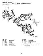
Page 24: ...3 8 24 2 11 11 10 9 9 4 4 5 6 3 3 1 2 1 1 1 9 9 8 tine_ipb_1 NOTE All component dimensions given in U S inches 1 inch 25 4 mm KEY PART NO NO DESCRIPTION KEY PART NO NO DESCRIPTION 8 74610616 Bolt Hex Hd 3 8 24 x 1 9 4460J Tine RH 10 132728 Hub Asm RH 17 11 6555J Tine RH REPAIR PARTS TILLER MODEL NUMBER 944 625930 TINE ASSEMBLY ...

Page 25: ... 6 110614X Decal Hand Placement 7 102180X Decal Shift Indicator 8 157984 Decal Cout Rot Tines 9 120076X Decal Warning Rotating Tines 10 168260 Decal Tine Depth Stake 11 162384 Decal Warning Tine Shield 196535 Manual Owner s English 196536 Manual Owner s French 9 5 11 7 REPAIR PARTS TILLER MODEL NUMBER 944 625930 DECALS 1 3 4 10 ...

Page 26: ...26 REPAIR PARTS TILLER MODEL NUMBER 944 625930 ENGINE HONDA MODEL NUMBER GC160QHA2 ...

Page 27: ...105 Shaft rocker arm 7 5580113 Valve in 8 5580121 Valve ex 9 5580139 Spring valve 10 1426980 Retainer in Valve spring 11 0294819 Screw tappet adj 12 0004598 Nut tappet adj 13 6315873 O ring 6 8X1 9 RECOIL STARTER KEY NO PART NO DESCRIPTION 1 6061204 Starter assy Recoil nh1 black 2 5580634 Knob recoil starter 3 5611454 Rope recoil starter 3 5X52 CARBURETOR KEY NO PART NO DESCRIPTION 1 3088416 Gaske...

Page 28: ...28 REPAIR PARTS TILLER MODEL NUMBER 944 625930 ENGINE HONDA MODEL NUMBER GC160QHA2 ...

Page 29: ...st 9 5610985 Crankshaft q type PISTON KEY NO PART NO DESCRIPTION 1 5655949 Ring set piston riken 6315717 Ring set piston teikoku 2 5580014 Piston 3 1426576 Pin piston 4 5580022 Rod assy 5 1431055 Bolt connecting rod 6 1431055 Clip piston pin 13mm AIR CLEANER KEY NO PART NO DESCRIPTION 1 5611025 Tube breather 2 6718159 Element air cleaner 3 5611314 Housing air cleaner 4 5580436 Gasket air cleaner 5...

Page 30: ...ION 1 7378482 Pump assy Fuel 2 3683646 Rubber supporter 107mm 3 5611306 Tube diaphragm 5 5655972 Tank fuel 6 1814698 Rubber b tank mounting 7 5655980 Joint fuel tube 8 1762962 Collar fuel tank setting 9 5611355 Stay a fuel tank 10 6673289 Cap assy Fuel tank 13 5655998 Tube fuel 14 5656004 Tube fuel return 15 1490408 Rubber rr Fender 16 5611686 Bolt stud f tank 17 1033497 Washer 8mm 18 5611702 Coll...

Page 31: ...31 SERVICE NOTES ...

Page 32: ...PRINTED IN THE U S A 196535 Rev 1 03 10 05 TR 02488 ...

Reviews: