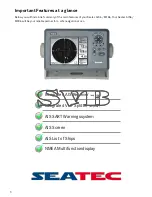
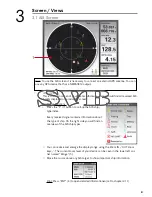
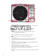
background image

2. 

AIS Reception LED


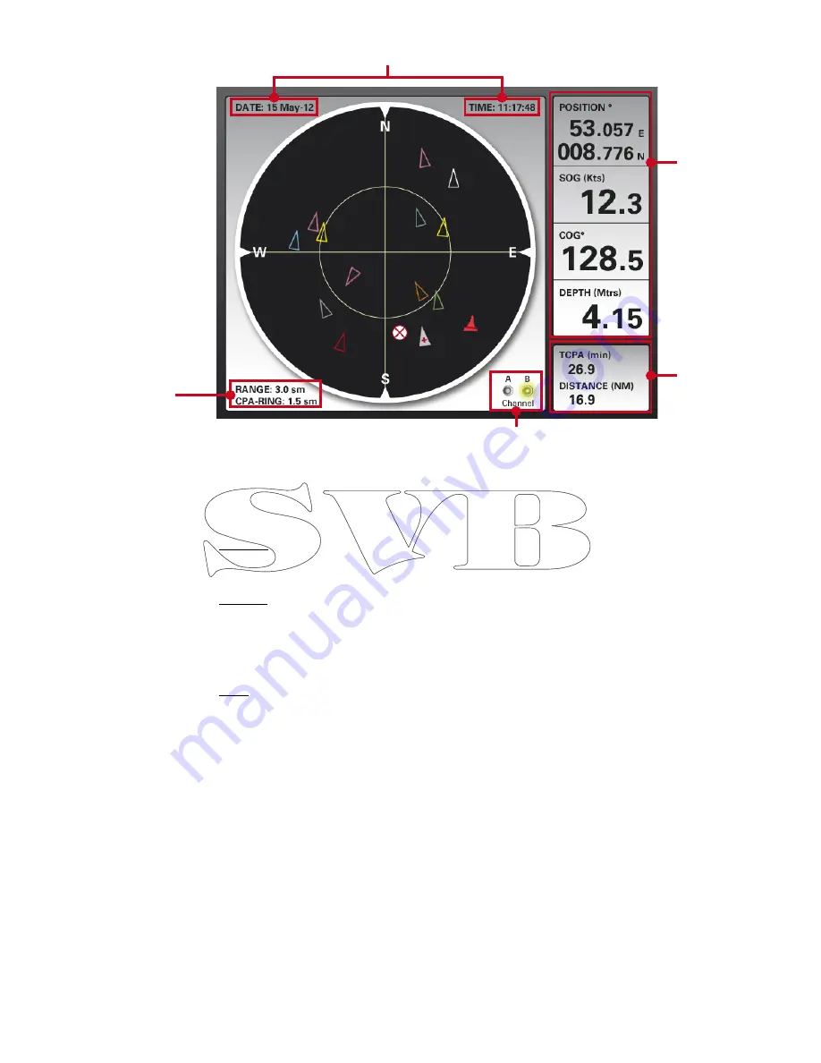
The Seatec AIS units are equipped with virtual reception LEDs. They start blinking  


when a class A or B AIS signal has been received. 


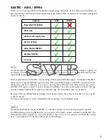
Class A: Signals of this class are sent mainly from commercial shipping.    


These signals contain more information than Class B signals.


Class B: These signals are normally transmitted by sport boats and contain  


  basic information about the boat. 


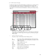
You will find a detailed list of the class A and B signals in chapter 3.1.1 


Hint:  Use the LED´s to check the function of the AIS receiver.

3. 

AIS Alarm Field


This field shows the distance (CPA) and the time (TCPA) to the next AIS alarm.


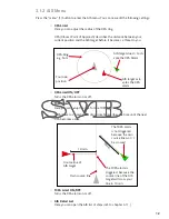
For more information about AIS alarms CPA and TCPA, see chapter 3.1.2

4. 

Data Field


Display of basic information such as position, speed over ground (SOG), course over  


ground (COG) and depth (received via NMEA).

5. 

Range / CPA-Ring


Range shows, in which radius AIS targets are displayed.


The CPA ring indicates the radius in which a CPA alarm will be activated for an AIS  


target. For more information on the CPA alarm, see chapter 3.1.2

6. 

Date / Time


Displays the current date and time (in UTC format), which is transmitted by the GPS  

 receiver.

9

5

4

3

2

6

Summary of Contents for AIS6

Page 1: ...User Manual AIS6 MFR6...

Page 2: ...he main features of your Seatec AIS6 MFR6 Your Seatec AIS6 MFR6 will be your reliable partner for a safe navigation at sea Integrated AIS Receiver only AIS6 Integrated VHF Splitter only AIS6 AIS Scree...

Page 3: ...he form of an acoustic warning Many AIS SART transmitter allow to send out an AIS SART TEST signal In order to quickly distinguish between a test and a real emergency signal TEST sig nals are displaye...

Page 4: ...ur Seatec device into a true multi functional display Important data can quickly and easily be displayed You can get a fast overview of the needed data The built in VHF splitter of your AIS6 permits y...

Page 5: ...cable assignment 2 1 AIS6 2 3 MFR6 3 Screens Views 3 1 AIS Screen 3 1 1 AIS List of Ships 3 1 2 AIS Menu 3 2 Compass 3 3 Wind Display 3 4 Highway 3 5 Multidata Display 4 Main Menu Settings 5 AIS SART...

Page 6: ...the current selection and shows AIS details of the selected AIS target 5 ESC Closing of windows exit of current menu Hint Use ESC to move a window back invers MODE function 6 MOB This key is not enga...

Page 7: ...NMEA Output Ground 3 VHF Antenna IN Connect your VHF Antenna here P L Plug Hint We recommend the VHF Antenna RA106 SVB Art 73101 4 VHF Antenna OUT Connect your VHF here Normally you will need a P L P...

Page 8: ...8 400 NMEA Output 7 Purple 38 400 AIS NMEA Input 8 White NMEA Output Ground 2 Power Connector You can connect the supplied 2 Pin powercable which includes a build in 0 5A here Pin Color Description 1...

Page 9: ...om keys The current zoom level of your device can be seen in the lower left cor ner named Range 5 Additional Functions Press the F 7 button to call up the AIS ship type index Every received signal con...

Page 10: ...he LED s to check the function of the AIS receiver 3 AIS Alarm Field This field shows the distance CPA and the time TCPA to the next AIS alarm For more information about AIS alarms CPA and TCPA see ch...

Page 11: ...our device indicates that more AIS targets are received than could be displayed on the first page In this case you can scroll down by using the 3 keys 2 Colums of the AIS List of Ships The AIS list of...

Page 12: ...tenna Besides class B signal information a Class A signal contains the following data ROT Rate of turn Destination ETA Eastimated time of arrival NAV Status Underway using engine Moored Limited maneuv...

Page 13: ...the TCPA Alarm TCPA Time to closest point of approach describes the time until the next CPA becomes active TCPA Limit ON OFF Turns the CPA alarm on or off AIS Detail List Here you can open the AIS lis...

Page 14: ...r disired data will open up Confirm your selection with ENT 4 3 2 Compass Position Current GPS position TTG Time to the next waypoint Bearing Bearing to the next waypoint Range Distance to the next WP...

Page 15: ...your desired data will open up Confirm your selection with ENT 4 Using the marine NMEA 0183 data protocol wind data can be imported from external instru ments into the Seatec devices The received dat...

Page 16: ...s to choose the data field you want to edit and press ENT 4 There is a list that opens and from which you can select the desired data Confirm your selection with ENT 4 Many autopilotes offer the possi...

Page 17: ...Represents the current speed over ground SOG which is transmitted through the GPS receiver 2 Depth Represents the current depth which is received via the NMEA interface 3 Speed though water Log Displa...

Page 18: ...o configure different alarms Press the ENT 4 button to switch an alarm signal on or off Anchor Alarm This lets you set and monitor your position in relation to an anchor point Until you leave this poi...

Page 19: ...en has been confirmed by pressing the ENT 4 key After confirming the window will close and the position of the AIS SART signal will be displayed on the AIS screen Access detailed information of the AI...

Page 20: ...llowing message The AIS SART TEST window contains the following information Press the ENT 4 button to disable the audible alarm and close the window You can review the title and time of the received A...

Page 21: ...XTE VWR VWT MWD Voltage 10 5 to 35 VDC Voltage drop 300 mA at 12V Current consumption 500 mA at 12V operating voltage Size incl bracket 1129mm H 199mm W 89mm T MFR6 150mm H 223mm W 87mm D AIS6 Weight...

Reviews: