background image

Summary of Contents for 8086 CPU

Page 1: ...Instruction Manual Model SCP2008 BOB6CPU 16 Bit Processor for the 5 100 Bus Rev S 10 1 80 Asaattla omputar Products Inc 1114 Industry Drive Seattle WA 98188 206 575 1830 ...

Page 2: ...res Configuration Options Technical Description 1 0 General 2 0 Features and Comparisons to IEEE Standard 3 0 S 100 Connector Layout 4 0 A C Characteristics Theory of Operation One Year Limited Warranty 2 3 3 5 5 5 9 10 14 21 ...

Page 3: ...osed position allows the CPU to look at the sXTN line to determine if the peripheral being accessed can do a sixteen bit transfer The open position forces the CPU to do all eight bit transfers The switch is provided because some of the early eight bit systems used this line 60 for another purpose The switch allows the user another capability as well It allows him to compare program execution time ...

Page 4: ...ur 1 0 devices use a 16 bit address the jumper should be in the 16 bit position Most existing I Q devices use addressing in which the lower and middle address bytes are the same The upper address byte A16 A23 is never used in I O addressing PHANTOM This CPU board generates a PHANTOM signal whenever it addresses memory locations located above the lowest 64K This signal may be used to disable older ...

Page 5: ...ristate by CDSB pin 19 while is never disabled The 8086 allows 3 clock cycles for memory access minus delays and setup time At 8 MHz 250 ns memory is required while at 4 MHz over 500 ns access time is allowed see section 4 If more time is required the card may be switched to insert a wait state in every bus cycle addition the line formerly named sSTACK pin 98 is driven with clock speed status high...

Page 6: ...ndard They allow the CPU to run without modification with ordinary 8 bit memory for easy upgrade with new 16 bit memory for high performance or even in a mixed environment e g 16 bit memories in time critical code areas 2 2 6 Oata Line Connector Connector 1 a 16 pin IC socket is provided to allow monitoring the data lines of the 8086 CPU chip Pins 1 to 16 of this socket are connected to ADO to AD1...

Page 7: ...slNP 46 sOUT 45 sWO 97 slNTA 96 sHLTA 48 sXTRQ 58 2 4 1 Status Driver Disable Hringing low SDSH pin 18 will disable the status drivers Clock speed status pin 98 may optionally be disabled by this signal if necessary to be consistent with its traditional definition as the sST ACK status line 2 5 Control Bus All control lines are in accordance with the proposed standard They are OUTPUTS PIN INPUTS P...

Page 8: ...ll not work A 16 pin socket directly connected to the 8086 s Address Data lines is provided with pins 1 16 wired to ADO AD15 respectively This may be used with an IMSAI front lJanel to observe 8 data bits at a time Only pins 9 through 16 of the IMSAI front panel connector are used To observe the low even data byte plug pins 16 to 9 into pins 1 to 8 of the socket the cable should extend downward Fo...

Page 9: ...E 19 CDSB 69 20 70 21 71 22 ADSB 72 RDY 23 DODSB 73 INT 24 74 HOLD 25 pSTVAL 75 RESET 26 pHLDA 76 pSYNC 27 pWAIT 77 pWR 28 78 pDBIN 29 AS 79 AO 30 A4 80 Al 31 A3 81 A2 32 A15 82 A6 33 A12 83 A7 34 A9 84 A8 35 DOl 85 Al3 36 DOO 86 A14 37 AIO 87 All 38 D04 88 D02 39 D05 89 D03 40 D06 90 D07 41 DI2 91 DI4 42 DI3 92 DI5 43 DI7 93 DI6 44 sMl 94 DI1 45 sOUT 95 DIO 46 sINP 96 sINTA 47 sMEHR 97 sWO 48 sHL...

Page 10: ...o Data out R Ready RDY XRDY SIXfN S Status bus V pSTVAL W pWR Y pSync names levels reaching the first level until the used Signal Levels H High L Low V Valid X Invalid For example TRVCH means Time from Ready becomes Valid until Clock goes High Times specified are in nanoseconds either minimum or maximum as appropriate for a worst case specification Times listed are for a 4 MHz clock for an 8 MHz c...

Page 11: ...AL low before pSYNC low 125 62 0 TVHVL pSTVAL pulse width high 120 58 50 TVLVH pSTVAL pulse width low 120 58 50 TVLYH pSTVAL low before pSYNC high 125 62 0 TYHVL pSYNC high before pSTVAL low 100 45 50 TAVYH Address valid before pSYNC 140 60 TSVYH Status valid before pSYNC 160 35 except sXI RQ 70 0 TSVVL Status valid before pSTVAL low 180 50 40 TDLAX TDLSX Address status hold after pDBIN 160 80 50 ...

Page 12: ... TCHYH TCHYL J 1 TYHVL I TVLYH TVLYL r TVHVL r TVLVH 1 I I TAVYH 111 I I TSVYH TDLAX TSVVL X TDHDL TDLSX TDHIV X TAVIV j TDLlX 1 f TOVWL TWLWH TWHOX ____ II I TVLWL 1 J TWLMH TWHML f pWR MWRITE DATA IN STATUS pDBIN DATA OUT ADDRESS pSTVAL pSYNC 12 ...

Page 13: ...pSYNC RDY XRDY SIXTN BUS CYCLE WITH ONE WAIT STATE pWAIT I I pDBIN I pWR 13 ...

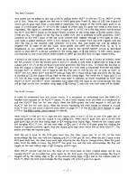
Page 14: ...ift register LOAD is also used to latch the three 8086 status lines and to set ALE high ALE Address Latch Enable is generated by half of U22 a D flip flop LOAD is used to set ALE high ALE clocks low on the next falling edge of the 8086 clock which is roughly the same as the rising edge of m2 ALE is used to latch the address output from the 8086 AD pins Since the AD pins are multiplexed address dat...

Page 15: ...o it The output of the NAND gate pin 6 of U32 now goes high since one of the inputs went low Therefore on the next rising edge of 2 WAIT goes low On the falling edge of T2 DONE goes high since WAIT has gone low When T2 went low T3 went high raising the J and K inputs pins 1 and 4 of U14 putting the ODDBT flip flop in the toggle mode On the next falling edge of 2 ODDBT goes low again indicating tha...

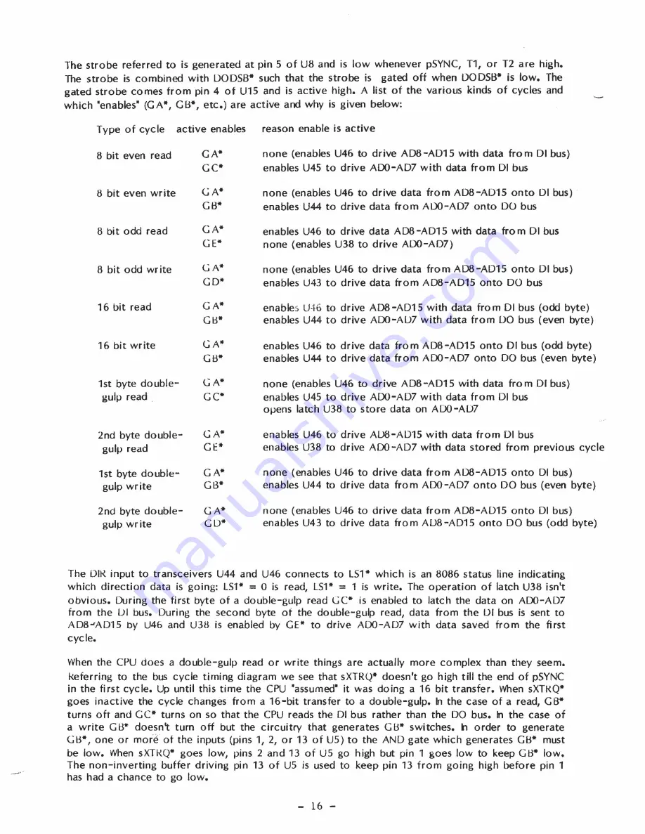
Page 16: ...15 with data from 01 bus enables U38 to drive ADO AD7 with data stored from previous cycle none enables U46 to drive data from A08 A015 onto 01 bus enables U44 to drive data from ADO AD7 onto DO bus even byte none enables U46 to drive data from AD8 A015 onto 01 bus enables U43 to drive data from AUB AD15 onto DO bus odd byte The 011 input to transceivers U44 and U46 connects to LS1 which is an 808...

Page 17: ...This holds the D input pin 12 of U7 low till that rising edge and adds one wait state in addition to those requested by RDY and XROY If RDY and XRDY never requested wait states then the input to the synchronizer flip flop will go high on the first available rising edge of ID2 during T2 and only one wait state will be added The Hold Circuitry In order to understand how this circuit works it is nece...

Page 18: ... always sets AO high and is only used during the second byte of a double gulp The gate inputs to each latch are connected to ALE to latch the address from the address data lines The four sections of U29 quad NAND provide the four output enables for the latches output enable 000 EVEN 10 MEM when active second byte of a double gulp all cycles except those when 000 is active all I O cycles when the I...

Page 19: ...ctivated to disable nonextended address memory in the first 64K Notice that the source for A16 A19 is the bus itself so that this circuit will operate for any bus master Also notice that it is NOT an open collector output and therefore if used should be the only PHANTOM driver in the system The POC and RESET Circuitry The power on c1ear circuitry actually consists of two seperate R C networks to p...

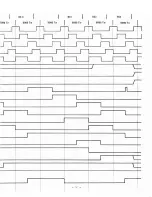
Page 20: ...3 8086Tw I I I I I I I I I I I I I I i I I I I I i i I I I I r I I I I I r I l I I I I I I J I I I I I I r I i i I 1 B DONE U23 5 IEEE BUS STATES 8086 T STATES 1 A 1 C 1 8086 1 2 SO S2 LOAD U5 6 ALE TO T1 T2 T3 pSYNC pDBIN pWR ODDBT ROY WAIT ...

Page 21: ...3086 T3 8086 Tw 8086 Tw 8086 Tw I 8086 Tw J 8086 T4 I I I I I I I t I I I I I I I I I I I I I I I I I I I I I I I I I I I I I I I I I I I I I I I I I I I r I I I I I I I I I I I I I I L I i I I I I I I I i I 20 I I I i ...

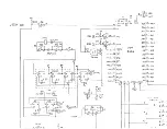
Page 22: ..._ AOI tN t v34 AD l 1 Atil BoB A II Ab8 LO ftb7 1 A 7 qs Atx ro b l tt I AH IS 11 IQn 04 A s Ss AI 1 AI l A f a r r R rr Z 27 I A 6V r I 4 1 P1 H l P tp TPS AI AI1 2 r R5 I 7 4L szo 1 2 I 3 T 1 F 1 or HV I I Z 4 lla 1 1 jo l L J q a C 7 I i _ s t AY p lilt k L J 2 11 1 DH c O I A 30 R 11V 1 1l R rv J 27 1 z 3 S t D t q rh L L__ w g _ 1 IHlIl It t 1 Ir l t tltS t t n I II II U St T ...

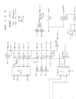
Page 23: ...a l I I l 11 r 19 V 2 VI I i 4 LJ uJ 7 r N a fr Q N 1 1 c41 j lP r c o t I c co V Q 1 C Z J s 1 I r 11 VI l n 0 0 1 ll t I a l U 3 q I r I rt oJ z II J c 0 C 01 0 r S It m on 0 T fi 10 10 0 v r j In r 1 IV1 c t 1 oJ I I r I a I r P et cD J r I G I J ...

Page 24: ... 1 1 13f II J oj I 1l 14 I ft1 yJ _ O 4 c JS 35 1 SI I u t 1 I 1 A i Z 10 Atl 1_1 8 7 I R S 5 1 0 r f _ tS P l j i 5 11 f _ IZ p 1 J L 1 1 32 ffC 6 3 18 14 II Ie fj 1 1 1 1 T 3 u F 1 2 f T PO B3 _ 7 1 M1 U 16 1 1 ...

Page 25: ...f I 1 lt1l I 1 3 1 3r wo ilp I C Q 1 S2 _1 1 I q I I 12 I ir il pw cf1 tS I 13 J t J 1 11 0 S 0 3 10 LO l Li r c t T 1 11 b Cll l IN l T9 9 I 1 r 1 t T Tl T2 T1 RQjr f 1 OISlllh z Gl J g Cf 1 5 fJA I 1J 2 I 21 _ 2 lfI S n ...

Page 26: ... J N I In I I 0 l N l ry C l I h i I p C o Le J C 1 T cs d a c c 4 ...

Page 27: ... 2 f B n 1 2 qiJ F I I A IQ L __ _ Pt 1 I D J 14 I _ _ _ _ AI S I 1 rr1 o I r t t _ i I I jTI t TI I T T t t t_ t J f i t P 1 3 12 lGo I h I 74L 3 7 A l 7 I b3 n _ I 11 Q I O t 3 17 b I e fWt 1 t 1 tll I O I l q 1 b t t3 J bl Sl 1 I I I I vI P _ _ b r t I I _ M_ I I I _ _ _ _ _ ...

Page 28: ...l hOi bo p5 ros Do7 bof I _ f I I _L __ f _ _ c I I _ _ I r _ _ I I 3 I 17 flt t 7 I r Q 1 11 l o L J1 S l bS I At I 3 1 I At g __ I f 7ItV L J A t IA b d1 1 13 f I lib 13 2 Abq 1 u 81 I I i 3 FI I 7 5 t i _ I 9 LSi De l 1 1 l 04 r 1 b 11 1 r t T li Jo blP rb l Q 1 02 1 1 1 so Hbl l 11 1 ...

Page 29: ...i _ _ _ _ _ _ _ _ _ _ I I dJ c o 0 0 I a ijJ I C r l r C Ie C D Q D IJ III 1 IIf r r r oJ U T l r C P i P P I P l et 4 4 8 i 1 i I 10 l ...

Page 30: ...ranty k1 the event the return of the board product or component is requested by SCP under this warranty the owner shall ship the item prepaid to the SCP factory SCP will pay for shipment of replacement items back to the owner All repairs or replacements under this warranty will be performed by SCP within five working days of receipt of notice of defect or return of components as called for under t...

Page 31: ......

Reviews: