Operating instructions HLE 500/5000
VI
MAN_HLE500_HLE5000_eng_02
List of illustrations
Fig 1 :
HLE 5000/500 control panel ...................................................5
Fig 2 :
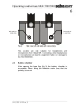
Side view left and right with connections................................6
Fig 3 :
Base plate with locking screws...............................................7
Fig 4 :
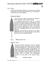
PAM U with sensor rod...........................................................9
Fig 5 :
PAM U with magnet................................................................9
Fig 6 :
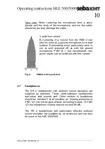
PAM U with 3-point foot........................................................10
Fig 7 :
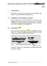
Start image with version number ..........................................11
Fig 8 :
Opening menu after switch-on..............................................12
Fig 9 :
Setting the volume................................................................12
Fig 10 :
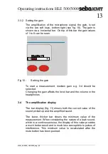
Setting the gain.....................................................................13
Fig 11 :
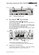
Current and minimum value .................................................14
Fig 12 :
Filter settings ........................................................................14
Fig 13 :
Adjusting the lower filter cut-off frequency............................15
Fig 14 :
Adjusting the upper filter cut-off frequency ...........................15
Fig 15 :
Dual segment analysis (DSA)...............................................17
Fig 16 :
Histogram measurement ......................................................17
Fig 17 :
Long-term measurement ......................................................18


