3-16
3.3
Connecting the Logger
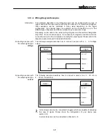
Depending on its configuration, the following peripheral and measring devices can be
connected to a logger:
•
up to 4 sensors can be attached and the data can be logged (e.g. pressure,
flow velocity)
•
up to 2 alarm-triggering devices (e.g. a light barrier) can be connected to the
switching inputs
•
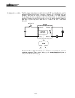
up to 2 devices (e.g. signal lamp, pump) can be connected to the switching
outputs and can be triggered in the case of an alarm
•
up to two tubes can be directly connected to the internal pressure sensors
Depending on the type of sensors / alarm devices connected to the Sebalog D, the
appropriate parameter values have to be provided to the logger using the
SebaDataView software. For a detailed description of the necessary configuration
steps, please refer to section 5.2.
3.3.1
Connecting Sensors and Alarm Devices
3.3.1.1 Basics
Introduction
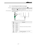
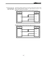
One end of the VK 75 / VK 76 connection cables used for connecting equipment to
the logger is uncoated and ten colour-coded wires stick out of it. According to its
colour, each of these wires represents a specific input / output of the logger and can
be directly connected to the respective terminal of a peripheral device (e.g. a sensor).
If no adequate terminals are existent, a luster terminal or other accessories can be
used. A proper electrical insulation must be ensured.
For the basic logger version with only one channel, all connections are established
via the VK 76 connection cable attached to the USB / DC ext. socket
.
For loggers with 2 or even 4 channels only the switching inputs/outputs and the
external power supply are connected via the VK 76 connection cable. Any
connections to sensors are established via the VK 75 connection cable attached to
the IN socket
.
The channels are assigned in numeric order which means that for a 2-channel
logger, the channels 1 and 2 have to be used for the connection setup.
3
4
Summary of Contents for Sebalog D
Page 2: ......


