3-21
3.3.1.4 Wiring Diagram Examples
Introduction
The examples described in the following pages can be realized with any type of
logger even with the basic version with only one channel. For multi-channel loggers,
these examples can be combined in many ways depending on the logger
configuration. A 4-channel logger, for example, can be connected to up to four
different types of sensors and can be included in up to two alarm loops.
Depending on the sensor, the actual wiring diagram and the terminal designation
may differ. For some sensor types, it is necessary to integrate a resistance into the
connection setup in order to dampen or amplify the output signal. Please refer to the
respective sensor manual for detailed information.
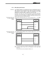
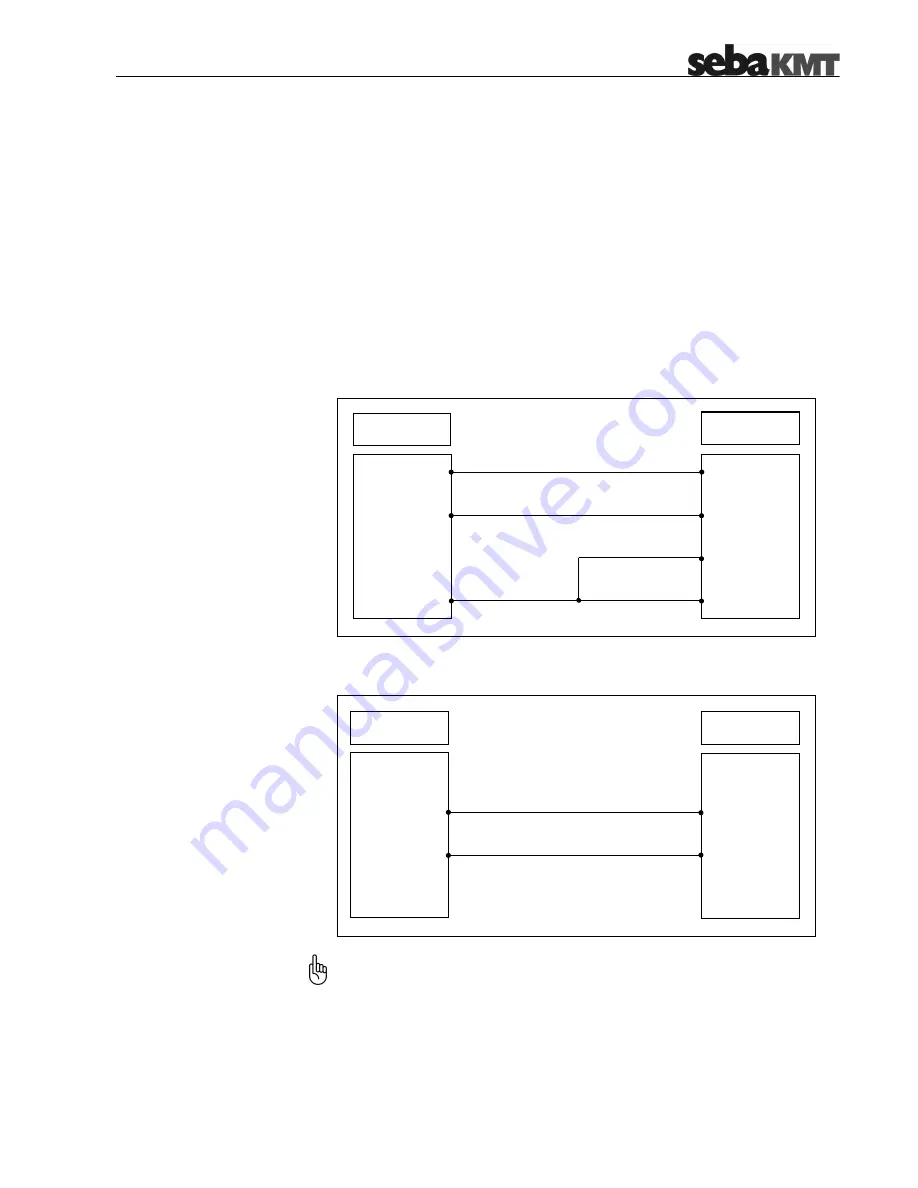
Connecting a sensor with
the output signal type
voltage
The following example describes how to connect a sensor with a 0 … 5 V voltage
output:
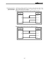
Connecting a sensor with
the output signal type
current
The following example describes how to connect a sensor to a 0 … 20 mA or
4 … 20 mA current loop:
Current loops can only be connected to loggers which are capable of analyzing
this type of signal. Please check the configuration of your device (see
section 2.3).
A current loop can only be connected to channel 2 or 4.
5 V OUT
C
GND
Channel –
Logger
I +
I –
Sensor
Sensor
Logger
5 V IN
Signal
GND
5 V OUT
C
GND
Channel
–
Summary of Contents for Sebalog D
Page 2: ......


