background image


72 


16 

Troubleshooting


If any problem appears which cannot be solved with the help of this user manual, contact our sales office and give a pre- 

cise description of the problem. Specify the type, the serial number and the firmware version of the transmitter. 

The display does not work at all or fails regularly


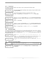
Check the contrast setting of the transmitter (see section 13.4). 
Check if the battery is inserted and charged. Connect the power supply. If the power supply is ok, the transducers or an in- 

ternal component of the transmitter are defective. The transducers and the transmitter have to be sent to SEBAKMT for 

repair. 

The message SYSTEM ERROR is displayed


Press key BRK to return to the main menu. 
If this message is displayed repeatedly, write down the number in the lower line. Track down the situations when the error 

is displayed. Contact SEBAKMT. 

The transmitter does not react when key BRK is pressed during the measurement


A program code has been defined. Press key C and enter the program code. 

The backlight of the display does not work, but all other functions are available.


Check if the backlight can be switched on by pressing the I/O key (see section 4.3). 
The backlight is defective. This problem does not affect the other functions of the display. Send the transmitter to 

SEBAKMT  for repair. 

Date and time are wrong, the measured values are deleted when the transmitter is switched off


The data backup battery has to be replaced. Send the transmitter to SEBAKMT. 

An output does not work


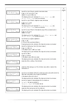
Make sure that the outputs are configured correctly. Check the function of the output as described in section 15.1.3. If the 

output is defective, contact SEBAKMT. 

A measurement is impossible or the measured values substantially differ from the expected values


see section 16.1. 

The values of the totalizer are wrong


see section 16.6. 


16.1 

Problems with the Measurement


A measurement is impossible because no signal is received. A question mark is displayed in the lower line on the 

right


• Check if the entered parameters are correct, especially the outer pipe diameter, the pipe wall thickness and the sound 

speed of the medium. (Typical errors: The circumference or the radius was entered instead of the diameter. The inner 

pipe diameter was entered instead of the outer pipe diameter.) 

• Make sure that the recommended transducer distance was adjusted when mounting the transducers. 
• Make sure that an appropriate measuring point has been selected (see section 16.2). 
• Try to establish better acoustic contact between the pipe and the transducers (see section 16.3). 
• Enter a lower value for the number of sound paths. The signal attenuation might be too high due to a high medium vis- 

cosity or deposits on the inner pipe wall (see section 16.4). 

The measuring signal is received but no measured values can be obtained


• An exclamation mark "

!

" in the lower line on the right indicates that the defined upper limit of the flow velocity is exceed- 

ed and, therefore, the measured values are marked as invalid. The limit has to be adapted to the measuring conditions or 

checking has to be deactivated (see section 11.4). 

• If no exclamation mark "

!

" is displayed, a measurement at the selected measuring point is not possible. 

Loss of signal during the measurement


• If the pipe had : Was there no measuring signal afterwards? Contact SEBAKMT. 
• Wait briefly until acoustic contact is reestablished. The measurement can be interrupted by a temporarily higher propor- 

tion of gas bubbles and solids in the medium. 

Summary of Contents for UDM-300

Page 1: ...Measuring and Locating Technologies Elektrizit tsnetze Power Networks Kommunikationsnetze Communication Networks Rohrleitungsnetze Water Networks Abwassernetze Sewer Systems Leitungsortung Line Locat...

Page 2: ......

Page 3: ...c Mess und Ortungstechnik GmbH Hagenuk KMT Kabelmesstechnik GmbH Dr Herbert Iann Str 6 D 96148 Baunach Phone 49 9544 68 0 Fax 49 9544 22 73 R deraue 41 D 01471 Radeburg Dresden Phone 49 35208 84 0 Fax...

Page 4: ...eby limited to a period of 12 months from the date of delivery Each component supplied by SebaKMT within the context of warranty will also be covered by this warranty for the remaining period of time...

Page 5: ...idioma de su elecci n ver secci n 8 5 Il est possible de s lectionner la langue utilis e par le transmetteur l cran voir section 8 5 The transmitter can be operated in the language of your choice see...

Page 6: ......

Page 7: ...ane Near an Elbow 23 6 INSTALLATION OF UDM 300 24 6 1 Location 24 6 2 Connection of the Transducers 24 6 3 Power Supply 24 6 3 1 Power Supply with the Battery 24 6 3 2 Power Supply with the Power Supp...

Page 8: ...on in the Measurement 44 11 7 3 Deactivation of the Program Code 44 12 DATA LOGGER AND TRANSMISSION OF DATA 45 12 1 Data Logger 45 12 1 1 Activation Deactivation of the Data Logger 45 12 1 2 Setting t...

Page 9: ...ulse Output 66 15 5 Activation of a Binary Output as an Alarm Output 67 15 5 1 AlarmProperties 67 15 5 2 Setting the Limits 68 15 5 3 Defining the Hysteresis 69 15 6 Behavior of the Alarm Output 69 15...

Page 10: ......

Page 11: ...tructions 1 3 Warranty The UDM 300 measuring instrument is guaranteed for the term and to the conditions specified in the sales contract provid ed the equipment has been used for the purpose for which...

Page 12: ...rticularly to the following points Protect the transmitter from shocks Keep the transducers clean Manipulate the transducer cables with caution Avoid excessive cable bend Make sure to work under corre...

Page 13: ...le depends on whether the flow is laminar or turbulent and is influenced by the conditions in the supply line of the measuring point see chapter 5 Reynolds number Re Coefficient describing the turbule...

Page 14: ...ess of the inner pipe wall The fluid mechanics correction factor is recalculated by the transmitter for each new measurement Mass flow rate m m V The mass of the medium that passes through the pipe pe...

Page 15: ...2 Sound path of the signal in the flow direction transducer receiver transducer emitter increase in distance in the transducer c c c pipe wall flow direction c of the medium sound path without flow so...

Page 16: ...The distance covered by the ultrasonic signal after crossing the pipe once The number of the sound paths is odd if the measurement is conducted in the diagonal arrangement see Fig 3 5 even if the mea...

Page 17: ...or more sound paths or beams see Fig 3 7 Fig 3 7 Sound paths in one plane 3 3 2 Examples Diagonal arrangement with 1 beam Reflection arrangement with 1 beam 1 transducer pair 1 sound path 1 transducer...

Page 18: ...opened to access the command panel RS232 interface state indicator charge state state indicator power supply 2 x 16 digit LCD display backlift keyboard Fig 4 1 Command panel of UDM 300 Fig 4 2 Connect...

Page 19: ...these three keys simultaneously to correct a malfunction The reset has the same effect as restarting the transmitter Stored data are not affected BRK interruption of the measurement and selection of...

Page 20: ...Avoid locations with deposit formation in the pipe The ambient temperature at the measuring point has to be within the operating temperature range of the transducers see annex B Select the location of...

Page 21: ...ottom or gas bubbles at the top of the pipe will not influence the propagation of the signal correct disadvantageous Vertical pipe Select the measuring point at a pipe location where the medium flows...

Page 22: ...w profile in the pipe is fully developed However measuring results can be obtained even if the recommended distance to disturbance sources cannot be observed for practical reasons Recommended straight...

Page 23: ...nt l recommended distance disturbance source T piece supply line l 50 D return line l 10 D l l disturbance source diffu supply line l 30 D ser l return line l 5 D l disturbance source valve supply lin...

Page 24: ...eam wider flow velocity and sound speed range compared to the reflection arrangement use in the presence of deposits on the inner pipe wall or with strongly attenuating media only 1 sound path smaller...

Page 25: ...e measuring point The sound beam plane see section 3 3 has an angle of 90 45 to the elbow plane The elbow is upstream of the measuring point With measurements in both directions The sound beam plane s...

Page 26: ...r power supply flashes red the battery is almost empty The capacity is sufficient for the display and storing of the current parameter record A measurement is no longer possible Charging the battery C...

Page 27: ...ry output optorelay Fig 6 2 and Tab 6 2 V Rc Uext Uext 32 V Ic 200 mA RS485 optional shield A B C 120 termination resistor Rext is the sum of all ohmic resistances in the circuit e g resistance of the...

Page 28: ...6 5 Connection of the Serial Interface RS232 The RS232 interface is located on the front panel of the transmitter see Fig 4 1 Connect the RS232 cable to the transmitter and the serial interface of the...

Page 29: ...e sensors 7 2 Orientation of the Transducers and Transducer Distance Mount the transducers onto the pipe in such way that the engravings on the transducers form an arrow see Fig 7 1 The transducer cab...

Page 30: ...sert the last ball of the chain into the slot on the upper side of the transducer shoe Place the chain around the pipe Tighten the chain and insert it into the other slot of the transducer shoe Procee...

Page 31: ...N DONE is dis played After the initialization the remaining settings of the transmitter can be reset to the default settings and or the stored mea sured values can be deleted Select yes to reset the r...

Page 32: ...nches see figure below For a detailed overview of the menu structure see annex A SYSTEM settings contains the following menu items set clock dialogs and menus measuring outputs storing signal snap ser...

Page 33: ...scroll through the upper line and select a list item Press key to scroll through the lower line and select a value for the selected list item Press ENTER 8 4 HotCodes A HotCode is a key sequence that...

Page 34: ...4 Spanish 909044 English 909049 German Depending on the technical data of the transmitter some of the languages might not be implemented When the last digit has been entered the main menu will be disp...

Page 35: ...ll Thickness Enter the pipe wall thickness Press ENTER 9 1 3 Pipe Material The pipe material has to be selected to be able to determine the sound speed The sound speed for the materials in the scroll...

Page 36: ...rial Change the value according to the condition of the inner pipe wall Press ENTER 9 2 Input of the Medium Parameters 9 2 1 Medium Temperature At the beginning of the measurement the medium temperatu...

Page 37: ...nt in diagonal arrangement on very small pipes a negative transducer distance is possible 9 6 1 Fine Adjustment of the Transducer Distance If the displayed transducer distance is adjusted press ENTER...

Page 38: ...oll until the transducer distance is displayed and check the dif ference between the optimum and the entered transducer distance Repeat the steps if necessary 9 6 3 Value of the Sound Speed The sound...

Page 39: ...of the arrow if the displayed volumetric flow rate is positive e g 54 5 m h The medium flows against the direction of the arrow if the displayed volumetric flow rate is negative e g 54 5 m h 9 9 Inte...

Page 40: ...viously is displayed first Select the unit of measurement of the selected physical quantity Press ENTER Press BRK to return to the main menu The further menu items of the program branch Output Options...

Page 41: ...d is calculated on the basis of the medium parameters medium selected in the program branch Parameter temperature dependence ok is equal to the expected value 20 of the expected value 20 of the expect...

Page 42: ...displayed in parentheses in the upper line followed by the entered transducer distance here 50 8 mm The optimum transducer distance might change during the measurement e g due to temperature fluctuat...

Page 43: ...tor Select the program branch Output Options Press ENTER until the menu item Damping is displayed Enter the damping factor Press ENTER Press BRK to return to the main menu 11 3 Totalizers Total volume...

Page 44: ...reset to zero manually 11 4 Upper Limit of the Flow Velocity Single outliers caused by heavily disturbed surroundings can appear among the measured values of the flow velocity If the outliers are not...

Page 45: ...rrection for the flow velocity is activated in Special Funct SYSTEM settings Measuring Flow Veloc ity Select normal to display and transmit the flow velocity with profile correction Select uncorr to d...

Page 46: ...ed To stop an ongoing measurement the complete program code has to be entered break code Enter the program code with the keys and Press ENTER If the entered program code is not valid an error message...

Page 47: ...er memory can be displayed see section 12 1 6 12 1 1 Activation Deactivation of the Data Logger Press ENTER until the menu item Store Meas Data is displayed Select yes to activate the data logger Pres...

Page 48: ...the storage mode Press ENTER If sample is selected the displayed measured value will be used for storing and online transmission of data If average is selected the average of all values measured durin...

Page 49: ...ured values can be stored The available data logger memory can be dis played Select Special Funct Instrum Inform Press ENTER The type and the serial number of the transmitter will be displayed in the...

Page 50: ...erface for the offline transmission of data Select Special Funct SYSTEM settings serial transmis Press ENTER until Send Offline via is dis played Select the serial interface for the offline transmissi...

Page 51: ...o change the transmission parameters Press ENTER Set the transmission parameters in the 3 scroll lists Press ENTER baud baud rate parity parity st number of stop bits The default transmission paramete...

Page 52: ...on Press ENTER Check the connections and make sure that the PC is ready to receive data 12 2 7 Offline Transmission of Data with the Program FluxData The measurement data in the data logger are transm...

Page 53: ...ave Select the series of measurement to be stored Click on OK Select the path on which the data should be stored Enter the file name Click on Save The file will be stored with the file extension flx S...

Page 54: ...ry storage interval one data line per activated measuring channel is transmitted The line will be transmitted if there are no measured values available for the storage interval Example With a storage...

Page 55: ...enus Press ENTER 13 2 1 Pipe Circumference Select on if the pipe circumference is to be entered instead of the pipe diameter in the pro gram branch Parameter Press ENTER If on has been selected for Pi...

Page 56: ...er distances are iden tical only the recommended transducer distance will be displayed if Transd Distance auto has been selected 13 2 4 Error Value Delay The error value delay is the time after which...

Page 57: ...displayed in the program branch Parameter It will be followed by the selected pressure indicated in parentheses a absolute pressure g relative pressure 13 3 Measurement Settings Select Special Funct S...

Page 58: ...t ter Press ENTER The type and the serial number of the transmitter will be displayed in the upper line The max available data logger memory will be displayed in the lower line here 18 327 ad ditional...

Page 59: ...ect Special Funct SYSTEM settings Measuring Calibration Press ENTER 14 2 1 Profile Bounds Select user if the profile bounds are to be defined If factory is selected the default pro file bounds will be...

Page 60: ...n data off to work without correction of the flow velocity and return to the menu item SYSTEM settings If on has been selected enter the slope If 0 0 is entered the correction will be deactivat ed Pre...

Page 61: ...nct SYSTEM settings Measuring Miscellaneous Press ENTER until the menu item Bad soundspeed is displayed Enter for each measuring channel the fixed upper limit of the sound speed Enter 0 zero to use th...

Page 62: ...number of decimal points is constant The max value of the totalizer is reduced with each additional decimal place decimal places max value max display 0 1010 9999999999 1 108 99999999 9 2 107 9999999...

Page 63: ...layed Instead of UNDEF it is also possible to display the last valid measured value Select Special Funct SYSTEM settings Measuring Miscellaneous Press ENTER until the menu item Keep display val is dis...

Page 64: ...e physical quantity source item to be transmitted from the source channel to the output If a binary output is configured only the list items Limit and Impuls will be displayed The source items and the...

Page 65: ...d which is to be output if the source item cannot be measured e g if there are bubbles in the medium Tab 15 2 Error output error value result Minimum output of the lower limit of the output range Hold...

Page 66: ...A 2 0 error output 2 mA t d 4 Select a list item for the error output Press ENTER If Other value has been selected enter an error value It has to be within the limits of the output Press ENTER The te...

Page 67: ...y is the time interval after which the error value will be transmitted to the output in case no valid mea sured values are available The error value delay can be entered in the program branch Output O...

Page 68: ...ss ENTER Enter a test value The value has to be indicated on the connected multimeter Press ENTER Select yes to repeat the test Press ENTER Example output current output output range 4 20 mA Zero Scal...

Page 69: ...t item in the lower line Press ENTER to store the settings Tab 15 4 Alarm properties alarm property setting description func switching condition MAX MIN QUANT ERROR OFF The alarm will switch if the me...

Page 70: ...rate 9 9 m h the measured value is not below the limit the alarm does not switch If the switching condition QUANT is selected in the scroll list func the limit of the output will have to be defined sw...

Page 71: ...of the display 15 6 2 Reset and Initialization of the Alarms After an initialization all alarm outputs will be initialized as follows Tab 15 5 Alarm state after an initialization func OFF typ NON HOL...

Page 72: ...or of a relay when the flow direction changes If there is an internal adaptationto changing measuring conditions e g to a considerable rise of the medium temperature the alarm will not switch Alarm ou...

Page 73: ...closed MAX HOLD NC Cont open MIN QUANT ERROR Example R1 15 6 6 Deactivation of the Output If the programmed output is no longer required it can be deactivated The configuration of a deactivated output...

Page 74: ...efective contact SEBAKMT A measurement is impossible or the measured values substantially differ from the expected values see section 16 1 The values of the totalizer are wrong see section 16 6 16 1 P...

Page 75: ...in the transmitter only serve as orientation The entered pipe roughness is not appropriate Check the entered value The state of the pipe should be taken into account Measurements on porous pipe materi...

Page 76: ...lly symmetric the flow profile is affected Change the transducer position according to the pipe deformation 16 6 Problems with the Totalizers The values of the totalizer are too high See Special Funct...

Page 77: ...ed selection whether the pipe is lined selection of the lining material This display will only be indicated if Lining YES has been selected input of the sound speed of the lining material range 600 65...

Page 78: ...antity selection of the unit of measurement for the physical quantity input of the duration over which a floating average of the measured values has to be determined range 1 600 s activation of the da...

Page 79: ...nus Proc outputs input of the pulse value value of the totalizer at which a pulse will be emitted This display will only be indicated if Pulse Output is activated input of the pulse width range 1000 m...

Page 80: ...ivation deactivation or setting of the menu items in the other program branches activation of the menu item for the input of the pipe circumference in the program branch Parameter X selection of the i...

Page 81: ...of measurement for the sound speed X SYSTEM settings Measuring selection of the displays for the settings of the measurement input of an upper limit of the flow velocity range 0 1 25 5 m s 0 m s no de...

Page 82: ...uperUser mode is activated X input of the offset range 0 900 m s 0 the default value 300 m s is used This display will only be indicated if the SuperUser mode is activated X activation of the overflow...

Page 83: ...the default value 3 000 is used This display will only be indicated if the SuperUser mode is activated and Pro file bounds user is selected request if an additional correction of the flow velocity is...

Page 84: ...irmware version with the date dd day mm month yy year X Program Code selection of the displays for the input of a program code defining a program code input of the break code program code input of the...

Page 85: ...t temperature 10 50 C display 2 x 16 characters dot matrix backlight menu language English German French Dutch Spanish measuring functions physical quantities volumetric flow rate mass flow rate flow...

Page 86: ...terial housing contact surface PEEK with stainless steel cap 316Ti 1 4571 PEEK PEEK with stainless steel cap 316Ti 1 4571 PEEK degree of protection according to IEC EN 60529 IP681 IP681 transducer cab...

Page 87: ...bic centimeter Sound speed unit of measurement description m s meter per second Kinematic viscosity unit of measurement description mm2 s square millimeter per second 1 mm s 1 cSt Flow velocity unit o...

Page 88: ...feet per hour MMCF Selection with HotCode 007027 firmware version V5 91 or higher cft cubic foot aft acre foot 1 US gal 3 78541 l 1 bbl 42 US gal 158 9873 l Volume totalized unit of measurement m3 m3...

Page 89: ...per hour klb klb m kilopound per minute klb 1 lb 453 59237 g 1 t 1000 kg Mass totalized unit of measurement t t kg kg kg g Mass flow rate unit of measurement description t h metric ton per hour t d m...

Page 90: ...V o l u m volumetric flow rate l l l l l l l l l volumetric flow rate l l l l l l l l l l S t r m u n g s g e s c h i d i k i t Flow Nomogram Metrical l 0 3 l 0 0 l 0 l 0 l 0 l l l 0 flow velocity m...

Page 91: ...volumetric flow rate 1 1 1 1 1 1 0 1 1 1 1 1 1 1 1 1 1 0 S t r m u n g s g e s c h w i n d i g k e i t f t s Flow Nomogram Imperial 1 0 5 1 0 4 1 0 3 1 1 0 0 1 0 1 1 0 1 0 0 flow velocity m s volumet...

Page 92: ...2 200 trans Titanium titanium 3 067 5 955 trans Copper copper 2 260 4 700 trans Aluminium aluminum 3 100 6 300 trans Brass brass 2 100 4 300 trans Plastic plastic 1 120 2 000 long GRP glass reinforced...

Page 93: ...and light metal 0 0 0015 drawn steel pipes 0 01 0 05 fine planed polished surface max 0 01 planed surface 0 01 0 04 rough planed surface 0 05 0 1 welded steel pipes new 0 05 0 1 after long use cleaned...

Page 94: ...988 0 4 181 60 1 983 2 4 184 70 1 977 7 4 190 80 1 971 6 4 196 90 1 965 2 4 205 100 1 013 958 1 4 216 120 1 985 942 9 4 245 140 3 614 925 8 4 285 160 6 181 907 3 4 339 180 10 027 886 9 4 408 200 15 55...

Page 95: ...ie z me nor da ka iztr d jumu uz kura t atrodas nedr kst izmest kop ar parastiem m jsaimniec bas atkritumiem T k tas ir izstr d jums ko cits citam p rdod un lieto tikai uz mumi tad to nedr kst ar izme...

Reviews: