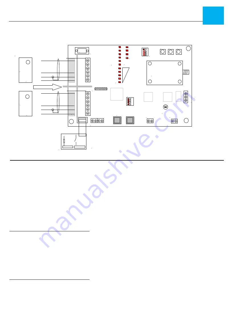
background image

RF Module

Tx

Rx

CTx1

CRx1

CTx2

CRx2

Cardax
readers

16 vac in

ADDR

LEDS

Expand Port 

SED-901 REMOTE
                CARDAX

MODE

D 9

POWER

CHARGE

LINK

MEMORY

A
B
C
D

on

COPY PROG TEST

Signa

RS232
@115k in

1

batt Volts
 

N0  

 C  

  NC

Battery  in

RS 485 Port

IN range relay

on

4 way i/o

board

+12  A   B   GND

+    --

xxxx   Reader
          beep
          Led
          Clock
          Data
          Comm
          Power

reader 1

reader 2

          blue
          na
          na
          white
          black
          red

          blue
          na
          na
          white
          black
          red

xxxx   Reader
          beep
          Led
          Clock
          Data
          Comm
          Power


SED-901 REMOTE CONNECTION  


DIP SWITCHES  
NOTE:


Mode switch sets Master or Remote 

and  Wiegand or Cardax  

1 A off   =  Remote 
2 B off  =   Wiegand 
3 C off =    not used  
4 D off =    Programming via Serial 8n115k 


NOTE: Address  switch used for expanders 
 

Cardax  READER 1  Connections 

BEEP=  

Cardax  BLUE 

LED =  

N/A 

CLOCK= 

N/A 

DATA = 

Cardax white  

COM= 

card reader GND or COMMON  

+12V= 

DC power for card reader  RED 


Battery in 

= 12v back battery 7 amp hr  

16v AC in 

plug pack where required 

RS 485 Port  

not used 


Fault relay 

Used for RF signal link when in Range   


DB 9 Serial   

for PC configuration  8,n,1 @115k 

RJ 45 EXPANDER Port 

Used to link boards via RJ 12 jumper cable 


Relay Board Operation 

The Relay System is simple - inputs on the  
Relay board follow outputs  

Example:

 If you trigger Input 1 on either  

Relay board, it will then trigger Relay 1 
on the opposite board  


   INSTALLATION - SED-901 Cardax Remote     


SED-901 MASTER Board Layout & Connections 

Note: The SED-901 has dual markings for 

MASTER & REMOTE


Cardax  READER 2  Connections 

BEEP=  

Cardax  BLUE 

LED =  

N/A 

CLOCK= 

N/A 

DATA = 

Cardax white  

COM= 

card reader GND or COMMON  

+12V= 

DC power for card reader  RED 

Summary of Contents for SED-901

Page 1: ...ot cover damage that has resulted in the improper installation or improper use of this product The warranty does not cover lightning damage product misuse electrical surges or acts of God LIMITATION O...

Page 2: ...f 3 metres away from each other or any other Antennas 3 If you are installing multiple SED 901 systems in one location call us so we can assist you with the best possible installation process and set...

Page 3: ...EIGAND IN Wiegand card readers 1 2 900m line of sight SED 901 Remote SED 901 Master Master Remote The SED 901 series will accept only card information such as a Wiegand data stream from 23 to 80 bits...

Page 4: ...rd reader LED BROWN CLOCK card reader CLOCK D0 WHITE DATA card reader DATA D1 GREEN COM card reader GND or COMMON 12V DC power for card reader RED READER 2 Connections BEEP card reader YELLOW LED card...

Page 5: ...1 Connections DATA DATA D1 GREEN CLOCK CLOCK D0 WHITE LED LED BROWN BEEP YELLOW COM GND or COMMON 12V DO NOT WIRE ACCESS CONTROL 2 Connections DATA DATA D1 GREEN CLOCK CLOCK D0 WHITE LED LED BROWN BEE...

Page 6: ...rdax READER 1 Connections BEEP Cardax BLUE LED N A CLOCK N A DATA Cardax white COM card reader GND or COMMON 12V DC power for card reader RED Battery in 12v back battery 7 amp hr 16v AC in plug pack w...

Page 7: ...ders ACCESS CONTROL 1 Connections DATA DATA 0 on Cardax White CLOCK N A LED N A BEEP OUT 1 on Cardax Blue COM GND or COMMON 12V DO NOT WIRE Battery in 12v back battery 7 amp hr 16v AC in plug pack whe...

Page 8: ...data Signal LED s 1 5 lowest to highest TX RX CTX1 CRX1 CTX2 CRX2 LEDS Power Charging Link Memory Signal MODE SWITCH TOP OF BOARD NOTE Mode switch sets if the unit is a Master or Remote Switch 1 ON 9...

Page 9: ...SET DIP SWITCHES Expander dip switch Address settings ADDR switch 1 2 3 4 1 2 3 4 Expander 1 ON Expander 11 ON ON ON Expander 2 ON Expander 12 ON ON Expander 3 ON ON Expander 13 ON ON ON Expander 4 ON...

Page 10: ...the Copy Prog buttons until the signal leds begin to flash The unit is now in self learning and is waiting to link with a remote 3 Press and hold the Copy Prog buttons on your remote expander until it...

Page 11: ...ards via RJ11 jumper cable External Antenna Supplied It is recommended that the external Antennas are mounted outside with clear line of sight between the two ends The Antenna should be mounted as hig...

Page 12: ...est an alarm input on the SED 901 Master Relay Board this should trigger a relay on the SED 901 Remote 3 Wiring the SED 901 MASTER Please note The Wiring on the SED 901 Master requires wiring to be co...

Page 13: ...te at the location where you require to install it and do a field test to ensure you have a steady signal light 6 If all tests worked ok proceed to install into desired outdoor environment ensure you...

Page 14: ...m Tx FREQUENCY RANGE 915 750 927 265 MHz Rx FREQUENCY RANGE 915 750 927 265 MHz Emission Designation 221K1F1D Duty Cycle 100 YEAR OF MANUFACTURE 2005 COUNTRY OF MANUFACTURE USA STANDARD S TO WHICH CON...

Reviews: