background image

SECO-LARM 

 Double-Door Electromagnetic Locks 

SECO-LARM U.S.A., Inc. 

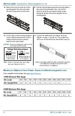
Guide pins 

TIP:

 Use a thread-locking compound on the armature


screws to ensure a long-lasting installation. 

Armature 

screw 

8.

  Tighten the armature screws enough so that 

the armature plates can withstand a break-in 
attempt, but loose enough so that the armature 
plates can pivot slightly. Make sure the anti-
spin guide pins are in the two guide pin holes. 

Metal 

washers 

The rubber washer will be 

sandwiched between the 

two metal washers

.


Short self-tapping screws 

Mounting Plate 

Armature Plate 

Long self-tapping 

screws 


7.

  Put a rubber washer between the two metal 

washers and place them over the armature 
screw between the armature plates and the 
doors. This allows the plates to pivot around 
the screw to compensate for door 
misalignment. 

9.

  Screw the four short self-tapping screws through the mounting plate’s slotted holes, but do not over-

tighten them. Keeping them loose will allow for adjustment of the plate left or right so that the mounting 
plate and the armature plates form a 90-degree angle. See the diagram below. 

10.

  Once the position of the mounting plate is 

correct, use the eight long self-tapping 
screws to permanently mount the 
mounting plate.


11.

  Drill the cable access holes. Run the power leads 

through the cable access holes in the mounting plate 
and through the holes in the door frame.


Summary of Contents for E-941D 600Q Series

Page 1: ...d bond sensor MOV surge protection Adjustable mounting bracket Complete mounting hardware for typical installations L bracket and Z brackets available for easy mounting Detachable faceplate 12 24VDC s...

Page 2: ...12 24 VDC Current draw 12VDC 500mA 12VDC per door 1A total 24VDC 270mA 24VDC per door 540mA total Bond sensor relay 1A 30VDC Dimensions Magnet 1911 16 x11 16 x15 8 500x26x40 mm 21 x15 8 x25 8 536x42x...

Page 3: ...ual will make installation much easier 2 The electromagnetic locks are designed for indoor use ONLY 3 The most suitable mounting location for the electromagnetic locks may require the use of additiona...

Page 4: ...ate side of the doors for the armature screws Then drill two 5 8 16mm dia holes for sexnut screws on the opposite side of the doors 5 8 16mm 5 16 8mm Hollow Metal Door Reinforced Door 1 4 6 8mm for M8...

Page 5: ...Put a rubber washer between the two metal washers and place them over the armature screw between the armature plates and the doors This allows the plates to pivot around the screw to compensate for d...

Page 6: ...24VDC Minimum Wire Gauge Wire Length 25ft 50ft 75ft 100ft 150ft 200ft 250ft 300ft 400ft 500ft 1000ft Wire Gauge 500mA 20 18 18 18 16 14 14 12 10 Wire Length 25ft 50ft 75ft 100ft 150ft 200ft 250ft 300f...

Page 7: ...unlocking Wiring Diagram A fail safe lock unlocks when power is lost so that in case of an emergency such as a fire in the building the fail safe lock will automatically unlock allowing personnel to...

Page 8: ...product are responsible for ensuring that the installation and configuration of this product complies with all national state and local laws and codes SECO LARM will not be held responsible for the u...

Reviews: