background image

SECO-LARM 

 Electromagnetic Locks 

SECO-LARM U.S.A., Inc. 

Installation 


1.

Fold the mounting template along the 
dotted line to form a 90-degree angle. 

Drill 3.2mm ( / ”) hole (2 places)

1 8

FOLD ON DOTTED LINE

PLACE AGAINST HEADER

Drill 8mm ( / ”) hole for cable access

5 16

Magnet

Drill 6mm ( / ”) hole for guide pins (12mm ( / ”) in depth)

1 4

1 2

PLACE AGAINST DOOR

Drill 8mm ( / ”) hole for armature screw

5 16

Armature

1200-lb Electromagnetic Lock

E-941SA-1K2DPSQ

MT_E-941SA-1K2DPSQ_210115.cdr

2.

Close the door. Find a mounting location 
on the door frame near the upper free-
moving corner of the door, or as close as 
possible to the upper corner of the door 
frame opposite the hinges.  

Ideal 

mounting 

location


Door frame


3.

Use a hammer to lightly 
tap the two guide pins into 
the guide pin holes on the 
armature plate. 

4.

Place the template against 
the door and frame. Mark 
where the holes are to be 
drilled.  

Door frame


Template


Door


5.

Drill holes in the frame and 
the door as shown on the 
template and in step #6 
below. The smaller holes on 
the door should not go all 
the way through. 

Door frame


Door 


See step 

#6 below


6.

Depending on the type of door being protected, drill holes according to the diagrams below: 

Drill a 

5

/

16

" hole (8mm) diameter hole 

through the armature-plate side of the 

door for the armature screw. Then drill a 

5

/

8

" (16mm) diameter hole for the sexnut 

screw on the opposite side of the door. 

Drill a 

1

/

4

" hole (6.8mm) 

diameter and 1" (25mm) 

deep hole, tap for 

M8x1.25 thread. 

Drill a 

5

/

16

" hole (8mm) diameter hole in 

the door for the armature screw and drill 

1

/

2

" (12.7mm) diameter and 1" (25mm) 

deep hole from the opposite side for the 

sexnut screw 

Reinforced door 

Solid-core door 

Hollow metal door 

5

/

8

" (16mm) 

5

/

16

" (8mm) 

1

/

4

" (6.8mm) for M8x1.25 thread 

1

/

2

" (12.7mm) 

5

/

16

" (8mm) 

Summary of Contents for E-941S 600DPSQ Series

Page 1: ...ensor With status LED and bond sensor With status LED bond sensor and timer MOV surge protection Adjustable mounting bracket Complete mounting hardware for typical installations L bracket and Z bracke...

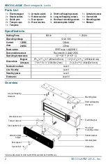
Page 2: ...s 1x Door spacer 2x Hex head mounting screws 1x Mounting plate 2x Tamper caps 2x Hex wrenches 1x Armature plate holder 1x Manual 1x Template Specifications Holding Force 600 lb 1 200 lb Operating volt...

Page 3: ...agnetic lock may require the use of additional SECO LARM accessories such as Z brackets L brackets and or spacer plates Please see the diagram on page 3 to decide if a particular application requires...

Page 4: ...armature plate 4 Place the template against the door and frame Mark where the holes are to be drilled Door frame Template Door 5 Drill holes in the frame and the door as shown on the template and in...

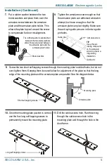
Page 5: ...htly Make sure the anti spin guide pins are in the two guide pin holes Guide pins Armature screw TIP Use a thread locking compound on the armature screw to ensure a long lasting installation Guide pin...

Page 6: ...your input voltage NOTES Failure to correctly set the input voltage may cause damage to the lock Connect switching devices like push to exit switches between the power source and the positive terminal...

Page 7: ...re Gauge 500mA 20 18 18 18 16 14 14 12 10 24VDC Minimum Wire Gauge Wire Length 25ft 50ft 75ft 100ft 150ft 200ft 250ft 300ft 400ft 500ft 1 000ft Wire Gauge 250mA 22 22 22 20 18 18 16 16 14 14 14 Wiring...

Page 8: ...operating properly as a result of causes other than defects in material and workmanship The sole obligation of SECO LARM and the purchaser s exclusive remedy shall be limited to the replacement or rep...

Reviews: