
Outdoor Wave-to-Open Sensors
SECO-LARM U.S.A., Inc.
3
Wiring Diagram
Installation
1.
Run four wires through the wall to a corresponding back box. Power must be provided by a low-
voltage power-limited/Class 2 power supply and low-voltage field wiring not to exceed 98.5ft (30m).
2.
Connect the 4 wires from the back box to the sensor according to the
Wiring Diagram
above.
3.
For weatherproof installation, use a waterproof back box and apply a bead of silicone sealant (not
included) around the rim of the back box and faceplate edge. Apply a small amount of sealant below
each screw head.
4.
Screw the plate into the back box, taking care not to crimp the wires and ensuring a good seal.
5.
Remove clear protective film from the sensor before use.
WARNING:
Do not connect any device that will exceed 1.2A@24VDC.
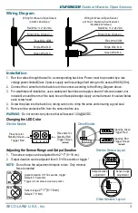
Changing the LED Color
Slimline Models
Other Models
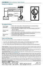
Adjusting the Sensor Range and Output Duration
1.
The sensor range can be adjusted from 2"~7" (5~18 cm).
2.
Output duration can be adjusted from 0.5~30 seconds or toggle.*
NOTE:
Do not force the adjustment trimpots to turn. Only minimal
force is needed
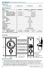
Red Wire: +12~24 VDC
Brown Wire: Ground (-)
Blue Wire: COM
Purple Wire: N.O.
Green Wire: N.C.
Red Wire: +12~24 VDC
Brown Wire: Ground (-)
Blue Wire: COM
Purple Wire: N.O.
Green Wire: N.C.
Wiring for Wave-to-Open Sensor
(SD-9263-KSQ shown)
Wiring for Wave-to-Open Sensor
with Form C Mechanical Override Button
(SD-9263-KSVQ shown)
Place here for:
Standby: Green
Trigger: Red
Standby: Green
Trigger: Red
Standby: Red
Trigger: Green
(default)
18cm
5cm
0.5s
30s
Output duration: 0.5~30 seconds, toggle*
Default: 0.5 seconds
*Toggle: turn clockwise to maximum position
Sensor range:
2"~7" (5~18 cm)
Default: 7" (18cm)
Place here for:
Standby: Red
Trigger: Green
(default)
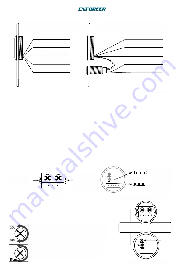
Slimline Sensor Layout
Other Sensors' Layout
Sensor range
adjustment
Output duration
adjustment


