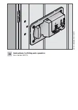
SECO-LARM Electric Door Strike with Vertical Adjustment
2
SECO-LARM U.S.A., Inc.
Specifications:
Parts List:
Quick Installation:
1x Door strike
5x Faceplates
1x Mounting template
2x Electrical connectors
2x Crimp connectors
2x Mounting tabs
1x Trim plate
2x Trim plate screws
2x Wood screws
6x Machine screws
2x Faceplate screws
2x Self-tapping screws
The SECO-LARM
SD-996C-NUVQ
Electric Door Strike with Vertical Adjustment is compatible with
a wide range of lock types including cylindrical, mortise, and mortise exit devices and can be configured for use
in wood, aluminum, or metal doors. Included are various ANSI-sized faceplates that can be easily installed on
the strike to match the door lock type and the strike is easily
field-configurable for fail-safe or fail-secure applications.
Model SD-996C-NUVQ
Operating voltage
12/24 VDC
Current draw
12VDC 300mA
24VDC 150mA
Operating temperature
14°~113° F (-10°~45° C)
Operating humidity
0~85%
Static strength
1,000 lbs. (454kg)
Dynamic strength
33 ft-lbs. (4.56 m-kgs)
Endurance
250,000 cycles (UL Tested), Level IV
Destructive attack
Level I
Line security
Level I
Standby power
Level I
Latch throw
1" (25mm) max with
1
/
8
" (3mm) door gap
Dimensions 1
13
/
16
"x1
5
/
8
"x3
5
/
16
" (47x42x84 mm)
Note:
Not all parts will be used in every installation.
1.
Select the type of faceplate that will be used. See "Sample Installations," on page 5. If the door is pre-cut
for a strike, skip to step 6.
2.
Measure and mark the door latch line and the center line of the door. See "Measuring the Latch Line &
Center Lines," page 3.
3.
Apply the included stick-on template to the door frame. See "Mounting the Template," page 3.
4.
Prepare the door frame for installation and mount the trim plate if needed. See "Preparing the Door
Frame" and "Mounting the Trim Plate," page 4.
5.
If the door frame material is unsuitable for mounting the strike directly, use the included mounting tabs for
installation. This is recommended for aluminum door frames. See "Mounting the Strike Using Mounting
Tabs," page 4.
6.
Program for either fail-safe or fail-secure operation. See "Selecting Fail-Secure or Fail-Safe," page 6.
7.
Connect power and complete installation to frame. See "Wiring Diagram," page 6.
8.
Adjust the keeper if needed to correct for any installation problems, page 7.
Introduction:


