

ENFORCER Access Power Distribution Boards
SECO-LARM U.S.A., Inc.
5
Installation (Continued):
iii.
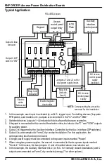
Connect the power supply's positive terminal to the power distribution board output
terminal for this device marked "C."
iv.
For fail-safe operation, connect the positive input of the powered device to the
terminal marked "NC."
v.
For fail-secure operation, connect the positive input of the powered device to the
terminal marked "NO."
c.
Unswitched auxiliary power outputs (to provide power to card readers, keypads, etc.)
i.
Connect the positive input of the powered device to the terminal marked "C."
ii.
Connect the negative input of the powered device to the terminal marked "COM."
NOTE:
Keep power limited wiring separated from non-power limited wiring (AC input, battery
wiring) by a minimum distance of
1
/
4
" (7mm) and use separate knockouts in the
enclosure.
5.
Connect each controlling device (card reader, keypad, RTE plate, etc.) to the corresponding
input terminal for the particular device to be controlled. Inputs are activated by normally open
or open collector sink inputs.
a.
Normally open (N.O.) input triggers:
i.
Connect the devices to the terminals marked "IN" and "GND" that correspond to the
power output terminals of the device to be controlled.
b.
Open collector sink inputs:
i.
Connect the access control panel open collector output to the power distribution
board's input terminal marked "IN."
ii.
Connect the access control panel open collector's common (negative) to the power
distribution board's input terminal marked "GND."
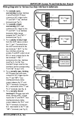
6.
Connect an Auxiliary Interface Control Panel (AICP) to the power distribution board's Aux.
Interface. A normally open, normally closed, or polarity reversal input from an AICP signaling
circuit will trigger selected outputs. To enable AICP disconnect for any output, set the
corresponding DIP switch for that output to "ON." To disable AICP disconnect for any output,
set its corresponding DIP switch to "OFF" (default, "OFF").
a.
Normally open (N.O.) input:
i.
For a non-latching hookup, refer to the instructions for Fig. 1 on pg. 7.
ii.
For a latching hookup, refer to the instructions for Fig. 4 on pg. 7.
b.
Normally closed (N.C.) input:
i.
For a non-latching hookup, refer to the instructions for Fig. 2 on pg. 7.
ii.
For a latching hookup, refer to the instructions for Fig. 5 on pg. 7.
c.
AICP signaling circuit input trigger
i.
For a polarity reversal input from the AICP Auxiliary Output, refer to the instructions
for Fig. 3 on pg. 7.
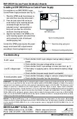
7.
The AICP Auxiliary Output may also be connected as a dry form C output as follows:
a.
Connect the device to be triggered by the unit's dry contact output to the power distribution
board's Aux. Interface terminals as follows:
i.
For normally open output, connect to the terminals marked "NO" and "C."
ii.
For normally closed output, connect to the terminals marked "NC" and "C."
NOTE:
The unit should be tested at least once a year for proper operation. Voltage on each output
should be tested for both triggered and untriggered states and the operation of the AICP
must be simulated.


