ENFORCER Access Power Distribution Boards
SECO-LARM U.S.A., Inc.
7
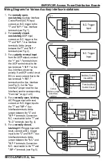
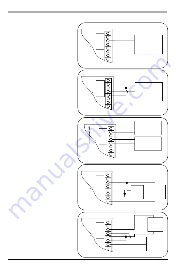
Wiring Diagrams for Various Auxiliary Interface Installations:
Fig. 2
N.C. Trigger
Input
INP
RET
NC
C
NO
T
–
+
–
+
Fig. 1
N.O. Trigger
Input
INP
RET
NC
C
NO
T
–
+
–
+
Fig. 3
INP
RET
NC
C
NO
T
–
+
–
+
Auxiliary Control
Circuit EOL
Cut Aux
Interface jumper
(intact=wet,
cut=dry)
–
+
ACP
From Auxiliary
Control Circuit
Fig. 4
INP
RET
NC
C
NO
T
–
+
–
+
N.C.
Reset
Switch
N.O.
Trigger
Input
Fig. 5
INP
RET
NC
C
NO
T
–
+
–
+
N.C.
Trigger
Input
N.O.
Reset
Switch
1.
For
normally open,
non-latching
Auxiliary Interface
Control Panel (AICP) input,
connect an N.O. trigger to the
"T" and "INP +" Aux. Interface
terminals (see Fig. 1).
2.
For
normally closed,
non-latching
AICP input,
connect an N.C. trigger to the
"T" and "INP –" Aux Interface
terminals. Add a jumper
between the "T" and "INP +"
terminals (see Fig. 2).
3.
For a
polarity reversal input
from the AICP output, connect
the "+" and "–" terminals from
the AICP control circuit to the
two terminals "+ INP –"on the
Aux. Interface, observing
polarity. If an AICP control circuit
EOL is used, connect that to the
two terminals "+ RET –"
terminals on the Aux. Interface
(see Fig. 3). Cut the "Aux
Interface" jumper near the Aux
Interface (see the corresponding
"Overview" on pg. 2 or 3).
4.
For a
normally open, latching
AICP trigger input with reset,
connect an N.O. trigger input to
the "T" and "INP +" Aux
Interface terminals. Add a
jumper between the "C" and
"INP +" terminals. Connect an
N.C. reset switch to the "T" and
"N.O." terminals (see Fig. 4).
5.
For a
normally closed,
latching
AICP trigger input with
reset, connect an N.C. trigger
input to the "C" and "INP –" Aux
Interface terminals. Add a
jumper between the "N.C." and
"INP +" terminals. Connect an
N.O. reset switch to the "T" and
" INP +" terminals (see Fig. 5).


