background image

22 

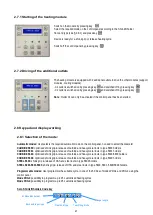
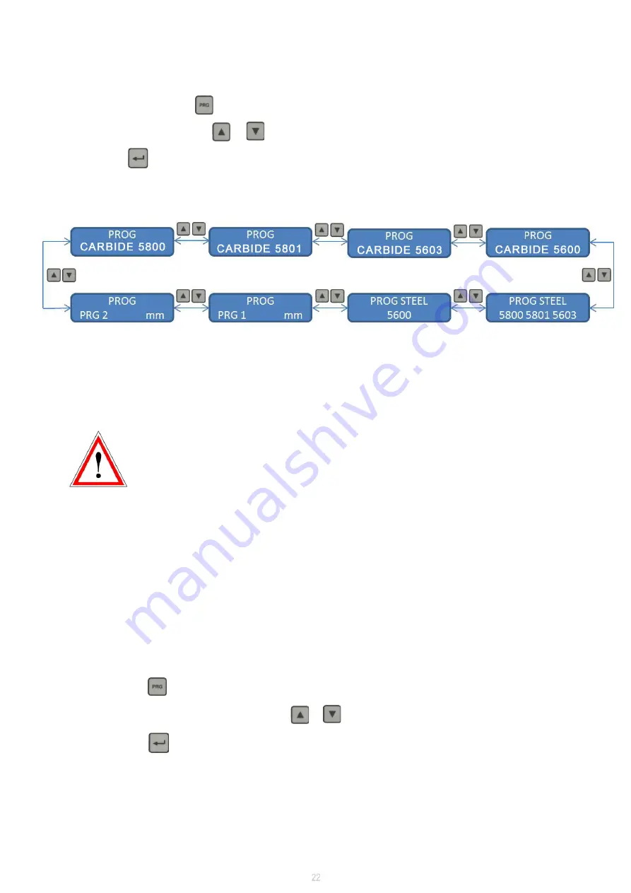
Selection of the required mode: 
 

On the control panel, press key 


Select the required mode using key         or           (see picture below) 


Then press key          to confirm your selection 


Device is ready for a shrink grip or release heating cycle. 

2.8.2 Using programmable modes PRG1 and PRG2 

Heating time modification 


In order to prevent misuse of these modes, the modification of the heating times is secured 

                          and an access code is required.  


By security measure, heating times of  PRG 1 and PRG 2 are preset to 0 second.  


The access code and the procedure to modify the heating times are given on request and 

                           after complete information about  the risks. 

 
Any change of the preset time must be made carefully, toolholder overheating makes it unusable. 

 In case of modification without our agreement, Seco Tools AB. cannot be held as responsible for any 

damage. 


Selection of the unit mm, inch, or mm and inch with mode PRG 1 or PRG 2: 
 

On the control panel, select mode PRG 1 or PRG 2 (see 

§

 above) 


Press two times key        . 


Choose between mm, inch, or mm and inch using key         or         . 


Press two times key          to confirm and come back to working mode. 

Summary of Contents for PACKS EASYSHRINK 20

Page 1: ...1 PACKS EASYSHRINK 20 OPERATING INSTRUCTIONS SHRINKFIT DEVICES ...

Page 2: ...er Seco EPB Working for Seco EPB s toolholders to be validated for others brands Provisions of warranty If your product proves to be defective although it has been used properly in accordance with the written Operating instructions manual supplied with it during a period of 12 months from the date of invoicing this product will be repaired or at Seco EPB s option replaced free of charge This warra...

Page 3: ...1 6 2 Contact bush for cooling bells 13 1 6 3 Air cooling cone 13 1 7 Other accessories 14 1 7 1 Tool supporting sleeve for stop rod 14 1 7 2 Stop screw setting adapter with hexagonal back end 14 1 7 3 Heat focusing stopper 14 2 PACKS INSTALLATION AND USE 15 2 1 Shrinking principle 15 2 2 Taking delivery 16 2 3 Localization of the module 16 2 4 Mounting 16 2 5 Connections 19 2 6 Starting 19 2 7 Co...

Page 4: ...ser guide for shrink grip of special toolholders 38 6 7 User guide for shrink release of special toolholders 38 7 TOOL SHRINKING DEPTH SETTING 39 7 1 Tool shrinking depth to be respected 39 7 2 Stop rod selection 39 7 3 Stop rod adjustment 40 8 DIRECT TOOL HEIGHT SETTING WITH DIGITAL RULE WITH DISPLAY 41 8 1 Overview 41 8 2 Description of the digital rule with display 41 8 3 Starting of the digita...

Page 5: ...early 48 10 SAFETY PRECAUTIONS 49 11 RECOMMENDATIONS FOR USE AND MAINTENANCE 49 12 SAFETY FUNCTIONS OF HEATING MODULES 49 13 ANNEXES 49 13 1 Technical features 50 13 2 CE compliance declaration for heating module to fill in 51 13 3 CE compliance declaration for support and cooling boxes to fill in 52 ...

Page 6: ...6 ...

Page 7: ...EE STATION ROTARY SUPPORT BOX WITH HEIGHT SETTINGS Always wear protective gloves while handling Shrinkfit holders tools accessories and spare parts Individuals who carry medical implants are banned from using or working with this device The carriers of a pacemaker must refer to the specific note of the pacemaker established on the basis of NF EN 60601 1 2 september 2007 Electrical hazard when dism...

Page 8: ...ating rotary plate of 3 operating shrink depth setting cooling stations Operating stations hold the finned supports with toolholder during the heating and cooling cycles All three stations are operating shrink depth setting and cooling stations while one station is used to shrink grip or shrink release the two others can be in cooling position Each station is equipped with a LED indicator which sw...

Page 9: ...d with A pair of gloves Five standard full set heat focusing stoppers for 3 to 32 mm their storage rack and adapter A set of 4 standard stop rods in a rack Operating instructions Additonal in Packs N 1 and 2 Two cooling cones 1 2 PACKS DELIVERY CONTENT The height measuring fittings include A fine adjustment of the sliding support using a height adjustment setting wheel A digital rule to control th...

Page 10: ...10 1 3 Dimensions Heating module Three station rotary support box Refrigerated water cooling bells unit Three station support box 1 operating and 2 cooling stations ...

Page 11: ...FCM08IN000 ZFAT08C_ _ Standard heat focusing stopper ZFAD05_ _ _ Finned support ZFAR07H_ _ _ Support ring ZFS07IN043 Stop rods set standard thread fitting ZFS07IN018 Stop rods set thin thread fitting STOP ROD ACCESSORIES FLANGE ACCESSORIES COOLING ACCESSORIES OTHER ACCESSORIES Z847031 Depth comparator for stop rod setting ZFS07IN282 Depth rulers for Shrinkfit depth setting for Shrinkfit holders Ø ...

Page 12: ...rator for stop rod setting Part No Z847031 User friendly measuring accessory to set stop rod s position for reliable Shrinkfit depth with EasyShrink 20 The distance between stop rod s front and holder s front face is directly readable on the comparator See Operating instructions 60Z847031U01 FR GB DE delivered with the depth comparator 1 4 4 Depth rulers for Shrinkfit depth setting A depth ruler i...

Page 13: ...ameters 5800 5801 5603 5600 Required to extract heat from the holder front end towards the liquid cooling bell 1 6 3 Air cooling cone Direct the air stream against the holder front end for cooling 1 5 Flange accessories 1 5 1 Finned supports Available for all types of toolholders SA30 to SA50 HSK25 to HSK100 Capto size C3 to C8 Required to provide positioning of the toolholder onto the support mod...

Page 14: ...lable for all tool shank diameters Ø 3 to 32 mm Useful for locating the cutter back end in contact onto the stop rod front end For use instructions see 8 9 1 7 3 Heat focusing stopper For positioning of the inductor housing Standard heat focusing stopper Pairs of split heat focusing stopper and ring Capacity Ø mm Standard heat focusing stopper Pairs of split heat focusing stopper 3 6 ZFAT08C01 ZFC...

Page 15: ...s the holder cools down the resulting thermal contraction exerts a tremendous uniform pressure around the entire surface of the tool shank Induction Induction heating allows clamping tools in a few seconds The 10 KW coil offers high performance The energy is sprayed very rapidely and remains concentrated on the clamping area Therefore there is less energy remaining in the holder cooling time is de...

Page 16: ...king has to be made carefully to avoid all damages 2 2 Taking delivery 2 3 Localization of the module The EASYSHRINK Pack is a table device to be localized in a dry and clean working place on a stable and rigid surface 2 4 Packs mounting Each support module is fixed with 4 pins side by side and are held by 4 pin point screws reachable at the location of the pins Screw the 4 pins in the side plate ...

Page 17: ...17 Mounting of support corner plate for heat focusing stopper Support corner plate for heat focusing stopper is fixed on the heating module left side plate with 2 screws supplied with the support ...

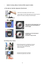
Page 18: ...properly aligned The inductor is ready to be used Unfavourable case the focusing stopper is out of alignment proceed to the following set of instruction B A Procedure to check the alignment of the inductor Unscrew the two lower screws of the inductor Unscrew the two upper screws of the inductor If the heat focusing stopper is out of alignment cf A above You have now access to the upper screws of t...

Page 19: ...PE 16 A 50 60Hz Differential breaker 30 mA 3 meter cable is supplied AC 1x230V PE 5A 50 60Hz cable with a DE FR electrical plug is supplied with support box For connections see paragraph 3 2 and 4 2 Additional for Pack N 3 AC 1x230V PE 5A 50 60Hz cable with a DE FR electrical plug is supplied with refrigerated water cooling For connections see paragraph 5 3 Air 3 to 6 bar pipe internal Ø 7 mm requ...

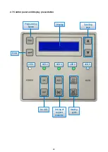
Page 20: ...20 Programming button Heating cycle Driving of support modules On Off Display Enter Scrolling keys LED 1 LED 2 LED 3 LED 4 LED 5 2 7 Control panel and display presentation ...

Page 21: ...e diameter CARBIDE 5800 optimised shrink grip release of carbide and heavy metal tools in type 5800 holders CARBIDE 5801 optimised shrink grip release of carbide and heavy metal tools in type 5801 holders CARBIDE 5603 optimised shrink grip release of carbide and heavy metal tools in type 5603 5803 holders CARBIDE 5600 optimised shrink grip release of carbide and heavy metal tools in type 5600 hold...

Page 22: ...ing times of PRG 1 and PRG 2 are preset to 0 second The access code and the procedure to modify the heating times are given on request and after complete information about the risks Any change of the preset time must be made carefully toolholder overheating makes it unusable In case of modification without our agreement Seco Tools AB cannot be held as responsible for any damage Selection of the un...

Page 23: ... 7 8 Ø 1 Ø 1 1 4 Ø X 1 Ø X 2 Scrolling in mm and inch Ø mm inch Ø 3 Ø 4 Ø 5 Ø 6 Ø 1 4 Ø 8 Ø 3 8 Ø 10 Ø 12 Ø 1 2 Ø 14 Ø 16 Ø 5 8 Ø 18 Ø 3 4 Ø 20 Ø 7 8 Ø 25 Ø 1 Ø 32 Ø 1 1 4 Ø X 1 Ø X 2 Ø X 1 Ø X 2 Diameter scrolling according to the selected unit Note Diameters X1 X2 X1 and X2 are not used in standard but they can be programmed for specific applications ...

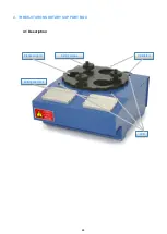
Page 24: ...24 3 THREE STATIONS SUPPORT BOX Setting wheel Cutting tool rack Flange support Ventilator 3 1 Description ...

Page 25: ...ator Ventilator driving is achieved by using the control panel of heating module Press key to switch on the ventilator Press key to switch off the ventilator Note X1 outlet is only working if the control panel is switched on press key 3 4 Driving of the cooling cycle Three station support box has 1 heating and cooling station and 2 cooling stations On completion of the heating cycle Install the to...

Page 26: ...26 Setting wheels LED Cutting tool rack Flange support Ventilators 4 1 Description 4 THREE STATIONS ROTARY SUPPORT BOX ...

Page 27: ...cycle Three station rotary support box with 3 LEDs timers Each LED is related to a cooling station On completion of the heating cycle and once cooling accessories are on the toolholder Switch plate with hot holder from the heating position to a cooling position by a 120 plate rotation Red LED will light on LED switches off automatically indicating the cooling process is finished unless a new rotat...

Page 28: ...ule directly go to the next page Using a 6 mm allen key unscrew the 3 screws that maintain the rotary plate Cut off every electrical energies Remove the rotary plate By default cooling times are preset to 200 sec However these cooling times can be adapted in step with the cooling system that is used see table on next page To do so coding wheels must be programmed to the required values ...

Page 29: ...s water cooling bells 2 min 120 s 0 2 1 finned cooling tubes 4 min 240 s 0 4 2 cooling cone 8 min 480 s 0 8 4 hundreds figure Cooling mode advised timing units figure tens figure Remove the 3 screws at the back of the module the 3 bottom screws on the side of the module BEWARE the upper screws are used to index the rotating plates They must not be unscrewed In order to access to the coding wheels ...

Page 30: ...30 5 REFRIGERATED WATER COOLING BELLS UNIT Flexible pipes Column Support for contact bush for cooling bells Cooling bells Cover of water tank Ventilation Water level Temperature control 5 1 Description ...

Page 31: ...ctrical cable on X2 outlet of heating module when switching on heating module water cooler will also start After installation and connection wait minimum 3 hours before turning on the power Never turn on the power without having filled the cooler before 5 2 Installation Water cooler must be localized on a stable working place respecting a clearance of 50 cm on both sides in order to allow air flow...

Page 32: ...in the tank with pure water tap water 7 5 pH 9 7 F TH 15 F until the indicator shows you that the tank is full Note change the water approx every 6 months 5 5 Starting 2 Select operating mode of water cooler B Remote water cooler driving is achieved by using control panel of heating module A Local water cooler driving is directly achieved by interruptor ON OFF at the rear After first use it might ...

Page 33: ... To modify the preset temperature press simultaneously SET et up arrow or down arrow As soon as the SET button is released the water temperature is displayed When the power is turned on the water cooler displays 88 during 3 seconds then displays the temperature of the water The water temperature is preset in our plant at 20 C It is adjustable from 10 C to 25 C In case of noticeable condensation it...

Page 34: ...hem downwards until rupture 4 Rotate disk C to release the station 5 Install the finned support or the support ring Water cooling module can be equipped with a cooling station 5 10 Remarks The tank must only be filled up with pure water tap water any other product is fobidden distilled water demineralized water glycol etc Should water cooler be idle for a long period device must be stored in an ar...

Page 35: ...20 25 Ø 32 mm 6 2 Shrink grip Through pneumatic actuation move the inductor housing downwards on the holder The heat focusing stopper must come in contact with the top of the toolholder Note recommended cylindrical tool shank tolerance is h5 or h6 maximum h5 for Ø 3 to 5 mm maximum h6 for Ø 6 to 32 mm 6 SHRINKING Select heating cycle corresponding to the Shrinkfit holder see 2 8 1 The heating cycl...

Page 36: ...it manually the tool in the bore The tool will be shrink grip within 3 to 5 seconds Note on completion of the heating cycle it is imperative to immediately remove the inductor housing from the tool in order to avoid heat spreading into the inductor housing risk of deterioration Always wear protective gloves while handling Shrinkfit holders tools accessories and spare parts 6 3 Shrink release Prepa...

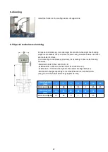
Page 37: ...ollowing conditions Maximal diameter of the cutter D is 3 x d Ø D maximum Ø 63 mm maximum bore Ø of induction unit A dimension 70 mm minimum due to the inductor housing dimension E dimension changes depending on tool shank diameter d see chart below see 1 8 3 for the Split heat focusing stoppers Part No 6 4 Cooling Install the holder on the cooling station of support box Tool shank d Ø mm 3 4 5 6 ...

Page 38: ...r assembly around the shank of the cutting tool Move the inductor housing upwards so that the split heat focusing stopper seat in the inductor housing location diameter Fit the lock ring Start the heating cycle as for a standard tool see 6 2 On completion of the heating cycle move the inductor housing upwards in order to extract the tool from the toolholder After shrinking remove the lock ring and...

Page 39: ...top end screw must be set minimum to l3 In this case the chart indicates l3 39 mm 7 2 Stop rod selection The proper stop rods in chosen depending on its size B B A D Note When using finned support for Shrinkfit holder taper SA50 ZFAD05S50 add 60 mm to the value B obtained Example for an Seco Shrinkfit holder type 5603 The diameter d and the jauge length are indicated on the toolholder E9343 5603 1...

Page 40: ...h comparator or depth ruler for depth measuring Note see also 8 9 8 10 tool length setting by using tool supporting sleeve for stop rod Select the suitable stop rod Example for a Seco Shrinkfit holder type 5603 We have determined in 7 1 that the jauge length of the toolholder is A 85 mm and the shrinking depth is D 40 mm B A D 85 40 45 mm In this case the suitable stop rod is the one in front of t...

Page 41: ...rt impulse on BP1 or BP2 Long impulse on BP1 or BP2 Keep pressure on BP1 or BP2 EASY AND PRECISE TOOL LENGHT SETTING Retractable comparator Digital display Adjusting wheel Display of REF I or REF II Button for BP 1 or BP 2 Display of MM or INCH Battery location Value of the rule Display of fixed value HOLD Display of Mode SET or PRESET ...

Page 42: ...arting of the digital rule 8 4 The different modes 8 5 Choice of the unit MM INCH Note modification only allowed in mode SET Note the digital display rule can not be deactivated in PRESET mode BP1 BP1 BP1 Off On ...

Page 43: ...ng BP1 BP1 To move the cursor BP1 Possibility to save negative values To increment the value BP1 2 different references can be saved REF I and REF II REF mode allows to fix a value by using key HOLD while moving the rule inductor housing moving Note value in INCH with 3 decimals rounded off by 0 or 5 To validate the saved value and return to mode s scrolling VALUE TO SAVE 249 66 MM Saved value mus...

Page 44: ...indle of the support module shrinking station Install the tool supporting sleeve onto the stop rod Install the cutting tool into the supporting sleeve Note the top of the stop rod must be in contact with the back end of the cutting tool if the cutting tool has a large bore for coolant through it might be necessary to select a longer stop rod to get into the tool shank Set the tool length by induct...

Page 45: ...ing capability Note 1 except SA50 which has a height of 110 mm hence its stop rod shrink depth capacity 0 to 180 mm 2 except Ø 32 Pack N 1 Pack N 2 Pack N 3 Minimum height between inductor and flange location 60 mm 40 mm Maximum height between inductor and flange location 565 mm 545 mm Flange mounts with fins height dimension Stop rod shrink depth capacity Digital rule stroke Digital rule display ...

Page 46: ...nce Check the water level of the water cooling unit Check the water temperature In case of important condensation it is advised to slightly increase the water temperature to prevent condensation on the bells and the tool holder Check the inductors condition Check the heat focusing plates condition Check the stop rods condition Not OK OK Not OK OK ...

Page 47: ...level is reached Empty the tank Waste water is considered as polluted and must be treated according to environmental constraints Close the tank back set the lid and screw it back Switch on the general switch at the back of the device Afterwards perform the running of the cooling unit from the heating module 9 3 Twice a year The water cooling unit must be drained off Turn off the general power supp...

Page 48: ...nd lubricant 9 4 Yearly The water cooling unit s condenser must be cleaned Using a 3 mm allen key remove the 16 screws of the water cooling unit s housing Move the housing away in order to access to the condenser beware the earth wire is connected to the housing Clean the condenser Set the housing and screw it back ...

Page 49: ...or 10 SAFETY PRECAUTIONS 11 RECOMMENDATIONS FOR USE AND MAINTENANCE 12 SAFETY FUNCTIONS OF HEATING MODULE Technical features Compliance declaration for heating modules support and cooling boxes to fill in Certificate 13 ANNEXES Always make sure the holder is cooled down before shrink grip or shrink release The holder and the tool must be clean free from grease and dry before being fitted into the ...

Page 50: ...cooled Water Flow rate of media 30 0 l min 1 7 bar Operating pressure max 3 5 bar Ambient temperature 10 0 C to 35 0 C Refrigerant R134a 0 310 kg Voltage 1x230V PE Ext on off signal 24 VDC Frequency 50 60 Hz Power 850 VA Weight 35 Kg 13 1 Technical features Temperature Air humidity Air pressure 3 Usage 10 to 40 C 10 to 90 1 800 to 1013 hPa Storage 20 to 55 C 30 to 95 800 to 1013 hPa Transportation...

Page 51: ...51 13 2 CE compliance declaration for heating module Fill in Part No and serial number ...

Page 52: ...52 13 3 CE compliance declaration for support boxes and cooling boxes one declaration per module Copy 1 Fill in Part No and serial number ...

Page 53: ...53 12 3 CE compliance declaration for support boxes and cooling boxes one declaration per module Copy 2 Fill in Part No and serial number ...

Page 54: ... this publication may be reproduced in any material form including photocopying or storing it in any medium by electronic means and whether or not transiently or incidentically to some other use of this publication without written permission of the copyright owner ...

Page 55: ...55 Seco EPB 8 BIS RUE DE NEUWILLER B P 6 67330 BOUXWILLER FRANCE TEL 33 0 3 88 71 38 89 FAX 33 0 3 88 70 98 98 WWW SECOTOOLS COM ...

Reviews: