CQ7-A30
CQ7-A30 - Rev. First Edition: 1.0 - Last Edition: 2.0 - Author: S.B. - Reviewed by G.G. Copyright © 2016 SECO S.r.l.
17
of order CQ7-A30 board, remove the batteries from the board in order to collect and dispose them according to the requirement of the same European Directive
above mentioned. When replacing the batteries, the disposal too has to be made according to these requirements.
2.3.2
Power Rails meanings
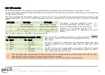
In all the tables contained in this manual, Power rails are named with the following meaning:
_S: Switched voltages, i.e. power rails that are active only when the board is in ACPI
’
s S0 (Working) state. Examples: +3.3V_S, +5V_S.
_A: Always-on voltages, i.e. power rails that are active both in ACPI
’
s S0 (Working), S3 (Standby) and S5 (Soft Off) state. Examples: +5V_A, +3.3V_A.
_U: unswitched ACPI S3 voltages, i.e. power rails that are active both in ACPI
’
s S0 (Working) and S3 (Standby) state. Examples: +1.5V_U
+5V_SB_Q7: Qseven Module Standby voltage. This power rail is used exclusively to supply the Standby power rail of the Qseven
®
module plugged in slot CN1.
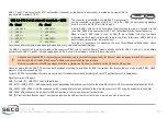
In all the cases when switched power rails are not required (inc5V_SB_Q7, it is possible to use the
jumper JP23, which is a
standard pin header, P2.54mm, 1x3 pin.
2.3.3
Power LEDs
In order to show the voltage presence of specific power rails, onboard there are five LEDs.
Red LED D18: +12V_A power rail active.
Red LED D19: +5V_A power rail active.
Green LED D21: +12V_S power rail active.
Green LED D22: +5V_S power rail active.
Green LED D23: +3.3V_S power rail active.
All five LEDs are off only when the board doesn
’
t receive any power supply input.
JP23 position AT/ATX mode
1-2
ATX mode (switched power rails
available)
2-3
AT mode (switched and always
power rails correspondence)


