background image


SBC-C43


SBC-C43 User Manual - Rev. First Edition: 1.0 - Last Edition: 1.0 - Author: A.R. - Reviewed by S.R. -Copyright © 2020 SECO S.p.A.  


33 


M.2 2230 Socket 1 Key E Connectivity Slot 

It is possible to increase the connectivity of the SBC-C43 
board by using M.2 Socket 1 Key E connectivity slot. 

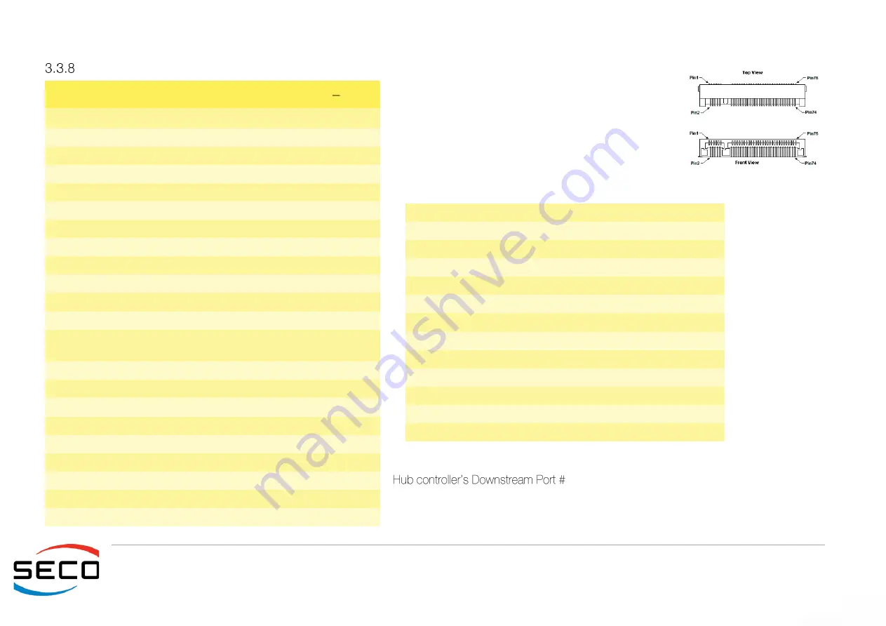
The connector used for the M.2 Connectivity slot is CN36, 
which  is  a  standard  75  pin  M.2  Key  E  connector,  type 
LOTES p/n APCI0076-P001A, H=4.2mm, with the pinout 
shown in the table on the left. 

On the SBC-C43 board there is also a Threaded Spacer 
which allows the placement of M.2 Socket 1 Key E connectivity modules in 2230 size. 


Signal Description 
 / USB_P2-: USB Port #2 differential pair; it is managed by Microchip USB4604 

2. 

P/PCIe1_Tx-: PCI Express lane #1, Transmitting Output Differential pair 
P/PCIe1_Rx-: PCI Express lane #1, Receiving Input Differential pair 
PCIe_K/ PCIe_KEYE_CLK-: PCI Express Reference Clock for lane #1, Differential 

M.2 Connectivity Slot (Socket 1 Key E type 2230)   CN36 

Pin  Signal 

Pin  Signal 

GND 

+3.3V_RUN 


+3.3V_RUN 

USB_P2- 

--- 

GND 

--- 

--- 

10 

--- 

11 

--- 

12 

--- 

13 

--- 

14 

--- 

15 

--- 

16 

--- 

17 

--- 

18 

GND 

19 

--- 

20 

--- 

21 

--- 

22 

--- 

23 

--- 

32 

--- 

33 

GND 

34 

--- 

35 

PCIe1_Tx0- 

36 

--- 

37 

PC 

38 

--- 

39 

GND 

40 

--- 

41 

PCIe1_Rx0- 

42 

--- 

43 

PC 

44 

--- 

45 

GND 

46 

--- 

47 

PCIe_K 

48 

--- 

49 

PCIe_ KEYE_CLK- 

50 

--- 

51 

GND 

52 

PCIE_RST1# 

53 

CLK_REQ1# 

54 

M2_KEYE_W_DIS2# 

55 

PCIe_WAKE1# 

56 

M2_KEYE_W_DIS1# 

57 

GND 

58 

M.2_KeyE_I2C_SDA 

59 

--- 

60 

M.2_KeyE_I2C_SCL 

61 

--- 

62 

M.2_KeyE_I2C_ALERT# 

63 

M2_KEYE_PRST# 

64 

--- 

65 

--- 

66 

--- 

67 

--- 

68 

--- 

69 

GND 

70 

--- 

71 

--- 

72 

+3.3V_RUN 

73 

--- 

74 

+3.3V_RUN 

75 

GND 


Summary of Contents for SBC-C43

Page 1: ...SBC C43 Single Board Computer with NXP i MX 8 Applications Processors...

Page 2: ...been made to ensure the accuracy of this manual However SECO S p A accepts no responsibility for any inaccuracies errors or omissions herein SECO S p A reserves the right to change precise specificat...

Page 3: ...9 1 8 Reference specifications 11 OVERVIEW 12 2 1 Introduction 13 2 2 Technical specifications 14 2 3 Electrical specifications 15 Power available 15 Power consumption 16 RTC Battery 16 Power rails n...

Page 4: ...onnectors 32 M 2 2230 Socket 1 Key E Connectivity Slot 33 M 2 SSD WWAN Slot Socket 2 Key B 34 microSIM Card Slot 36 microSD Slot 36 CAN Connectors 37 Expansion connectors 38 A D Header 39 Debug UART C...

Page 5: ...dition 1 0 Last Edition 1 0 Author A R Reviewed by S R Copyright 2020 SECO S p A 5 Warranty Information and assistance RMA number request Safety Electrostatic discharges RoHS compliance Terminology an...

Page 6: ...ne The RMA authorization number must be put both on the packaging and on the documents shipped with the items which must include all the accessories in their original packaging with no signs of damage...

Page 7: ...ter it is possible to send the faulty product to the SECO Repair Centre In this case follow this procedure o Returned items must be accompanied by an RMA Number Items sent without the RMA number will...

Page 8: ...ng RoHS compliant components and is manufactured on a lead free production line It is therefore fully RoHS compliant Always switch the power off and unplug the power supply unit before handling the bo...

Page 9: ...GPU Graphics Processing Unit HDMI High Definition Multimedia Interface a digital audio and video interface I2C Bus Inter Integrated Circuit Bus a simple serial bus consisting only of data and clock l...

Page 10: ...n Ethernet MAC and a PHY SATA Serial Advance Technology Attachment a differential half duplex serial interface for Hard Disks SD Secure Digital a memory card type SM Bus System Management Bus a subset...

Page 11: ...datasheets BreakoutBoards I2SBUS pdf LVDS http www ti com ww en analog interface lvds shtml http www ti com lit ug snla187 snla187 pdf M 2 Specifications https pcisig com specifications pciexpress M 2...

Page 12: ...43 User Manual Rev First Edition 1 0 Last Edition 1 0 Author A R Reviewed by S R Copyright 2020 SECO S p A 12 Introduction Technical specifications Electrical specifications Mechanical specifications...

Page 13: ...o Gigabit Ethernet interfaces The communication networking capabilities of the board are completed by an M 2 Key B Slot which allows plugging M 2 Modem modules with USB or PCI e interface an M 2 Key E...

Page 14: ...module M 2 Socket 2 Key B Slot for M 2 Modems M 2 Socket1 Key E Slot for WiFi BT external modules USB 1 x USB 3 0 Host port on Type A socket 1x USB 2 0 OTG port on micro AB socket 1x USB 2 0 Host port...

Page 15: ...n the table below Power available When powering SBC C43 with a PSU with characteristics greater or equal to the one described at beginning of previous paragraph please consider well what is the typica...

Page 16: ...hargeable CR1225 Lithium coin cell battery with a nominal capacity of 48mAh to supply such an RTC The battery must be plugged on the onboard battery holder CN43 In case of exhaustion the battery shoul...

Page 17: ...Power rails naming convention In all the tables contained in this manual Power rails are named with the following meaning _RUN Switched voltages i e power rails that are active only when the board is...

Page 18: ...1 0 Last Edition 1 0 Author A R Reviewed by S R Copyright 2020 SECO S p A 18 2 4 Mechanical specifications Board dimensions are 146 x The printed circuit of the board is made of ten layers some of the...

Page 19: ...I2S Audio Codec Flash QSPI uSDHC_1 USB_OTG_1 CSI_0 CSI_1 USB_SS RGMII 0 1 USB_HSIC SATA PCIe1 Expansion connector SAI_1 LVDS HDMI_OUT USB 2 0 internal connector eMMC Drive UARTs Optional eDP connecto...

Page 20: ...SBC C43 SBC C43 User Manual Rev First Edition 1 0 Last Edition 1 0 Author A R Reviewed by S R Copyright 2020 SECO S p A 20 Introduction Connectors overview Connectors description...

Page 21: ...osure Please be aware that depending on the configuration purchased the appearance of the board can be significantly different from the following pictures BOTTOM SIDE TOP SIDE Power IN GbE 1 USB 2 0 G...

Page 22: ...CAN Bus 1 Connector CN26 External Antenna u FL Connector CN48 CAN Bus 2 Connector CN28 micro HDMI Out Connector CN49 Expansion connector 1 CN29 micro HDMI In Connector CN50 Expansion connector 2 CN34...

Page 23: ...for HDMI panel Bidirectional signal electrical level 5VHDMI with a 2 up resistor SCL DDC Clock line for HDMI panel Output signal electrical level 5VHDMI with a 2 up resistor CEC HDMI Consumer Electro...

Page 24: ...HDMI panel Bidirectional signal electrical level 5VSINK with a up resistor SCL DDC Clock line for HDMI panel Output signal electrical level 5VSINK up resistor CEC HDMI Consumer Electronics Control CE...

Page 25: ...tory configurations please take care of specifying which is the configuration needed for LVDS_VCC_LCD_SW and LVDS_VCC_BKL_SW voltage rail When building a cable for connection of LVDS displays please t...

Page 26: ...lectrical level LVDS_VCC_LCD_SW with a10 up resistor LVDS_PANEL_ON LCD Panel enable signal electrical level to LVDS_ up resistor DISPLAY_BKL_ON Backlight enable signal electrical level to LVDS_ up res...

Page 27: ...are factory configurations please take care of specifying which is the configuration needed for EDP_VCC_LCD_SW and EDP_VCC_BKL_SW voltage rail Here following the signals involved in eDP management eD...

Page 28: ...ver to use camera modules with onboard crystal oscillator and avoid using this signal Indeed it could cause problems for EMI compliance requirements MIPI_CSI0_I2C0_SCL general purpose I2C Bus clock li...

Page 29: ...ernal camera module reset signal output it is an active low signal TRSS Audio jack On SBC C43 board audio functionalities are controlled by an I2S Audio Codec type TLV320AIC3204IRHBR It is possible to...

Page 30: ...Mbps modes ETH1_MDI2 ETH1_MDI2 Ethernet Controller Media Dependent Interface MDI I O differential pair 2 It is the third differential pair in Gigabit Ethernet mode it is not used in 10 100Mbps modes E...

Page 31: ...2 Ethernet Controller Media Dependent Interface MDI I O differential pair 2 It is the third differential pair in Gigabit Ethernet mode it is not used in 10 100Mbps modes ETH0_MDI3 ETH1_MDI3 Ethernet C...

Page 32: ...n the table on the left Depending on the needed use of the system it is necessary to connect micro A or micro B USB cables to connector CN44 A micro A USB cable has to be used when the system has to w...

Page 33: ...Port 2 differential pair it is managed by Microchip USB4604 2 PCIe1_Tx PCIe1_Tx PCI Express lane 1 Transmitting Output Differential pair PCIe1_Rx PCIe1_Rx PCI Express lane 1 Receiving Input Differenti...

Page 34: ...module is inserted in the slot Active low signal electrical level 3 3V_RUN with a 100K pull up resistor M 2 SSD WWAN Slot Socket 2 Key B The mass storage capabilities of the SBC C43 board are complet...

Page 35: ...l up resistor PCIe_WAKE0 up resistor It must be externally driven by the Connectivity module plugged in the slot when it requires waking up the system Here following the signals related to the USB int...

Page 36: ...for the connection to their network The socket is type MOLEX p n 78800 0001or equivalent with the pinout shown in the table on the left Signal are described in the above paragraph microSD Slot The i...

Page 37: ...MOLEX 51021 0600 receptacle with MOLEX 50079 8000 female crimp terminals On these connectors the pins CANx_L_TERM and CANx_TERM can be used to insert the 120Ohm termination at the end of CAN line Whe...

Page 38: ...CTS Serial Port 3 Clear to Send handshaking signal can be available at RS232 or TTL level factory alternatives TTL_GPIO_UART2_TX GPIO or Serial Port 2 Transmit data TTL level TTL_GPIO_UART2_RX GPIO or...

Page 39: ...ctrical level 3 3V_RUN SPI3_SCK SPI Serial Clock electrical level 3 3V_RUN GPIO_ 2 5 General purpose IO electrical level 3 3V_RUN SCU_UART0_TX Serial Port 0 Transmit data TTL level SCU_UART0_RX Serial...

Page 40: ...in single line SMT connector type MOLEX 53398 1071 or equivalent with pinout shown in the table on the left Mating connector MOLEX 51021 1000 receptacle with MOLEX 50079 8000 female crimp terminals Po...

Page 41: ...SBC C43 SBC C43 User Manual Rev First Edition 1 0 Last Edition 1 0 Author A R Reviewed by S R Copyright 2020 SECO S p A 41 Thermal Design...

Page 42: ...mbled system and the application The customer must always ensure that the heatspreader heatsink surface temperature remain within the declared operating temperature r ange at any point of the cooling...

Page 43: ...BC C43 User Manual Rev First Edition 1 0 Last Edition 1 0 Author A R Reviewed by S R Copyright 2020 SECO S p A 43 SECO S p A Via A Grandi 20 52100 Arezzo ITALY Ph 39 0575 26979 Fax 39 0575 350210 www...

Reviews: