SBC-C43
SBC-C43 User Manual - Rev. First Edition: 1.0 - Last Edition: 1.0 - Author: A.R. - Reviewed by S.R. -Copyright © 2020 SECO S.p.A.
34
Pair
PCIe_WAKE1#: Board s Wake Input, it must be externally driven by the module inserted in the slot when it requires waking up the system. Active low signal, electrical
level +3.3V_RUN with a 47K pull-up resistor
CLK_REQ1#: PCI-e Clock Request Input. Active low signal, electrical level +3.3V_RUN with a 47K pull-up resistor. This signal shall be driven low by any module
inserted in the connectivity slot, in order to ensure that the SoC makes available the reference clock.
PCIE_RST1#: Reset Signal that is sent from the SoC to all PCI-e devices available on the board. It is a +3.3V_RUN active-
-down.
KEYE_W_DISABLE1#: M.2 Key E Wireless module functionality disable signal #1, active low signal
KEYE_W_DISABLE2#: M.2 Key E Wireless module functionality disable signal #2, active low signal
M.2_KeyE_I2C_SDA: I2C Bus data line. Bidirectional signal, electrical level +1.8V_RUN
-up resistor.
M.2_KeyE_I2C_SCL: I2C Bus clock line. Bidirectional signal, electrical level +1.8V_RUN
-up resistor.
M.2_KeyE_I2C_ALERT#: I2C Bus Alert. Input signal, electrical level +1.8V_RUN
-up resistor.
M2_KEYE_PRST#: M.2 Key E input for detection when a module is inserted in the slot. Active low signal, electrical level +3.3V_RUN with a 100K pull-up resistor.
M.2 SSD/WWAN Slot: Socket 2 Key B
The mass storage capabilities of the SBC-C43 board are
completed by an M.2 SSD Slot, which allow plugging M.2
Socket 2 Key B Solid State Drives.
The same slot can be used alternatively for the connection of
Connectivity modules, using PCI-e x2 interface or USB 2.0
interface (USB interface is always available, while SATA
interface is alternative to PCI-e interface).
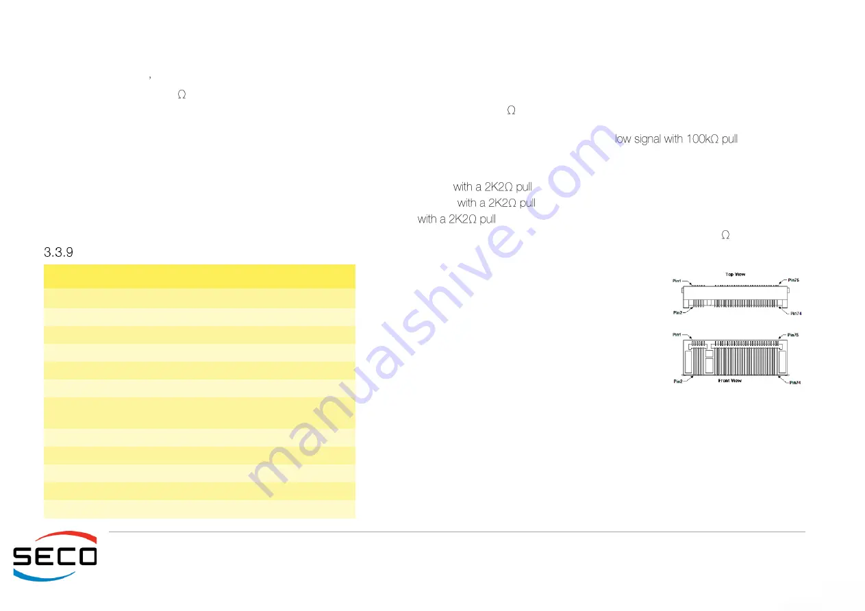
The connector used for the M.2 SSD slot is CN37, which is a
standard 75 pin M.2 Key B connector, type LOTES p/n
APCI0087-P001A, H=8.5mm, with the pinout shown in the
table on the left.
On the SBC-C43 board there is also a Threaded Spacer which allows the placement of M.2
Socket 2 Key B SSD modules in 2260 size.
It is possible to place also modules in 2242 / 3042 size, by using a M/F Spacer which allow
fixing the M.2 SSD on the spacer already available on the PCB, deemed for the fixing of the
M.2 connectivity slot (see previous paragraph).
Here following the signals related to the SATA interface:
S/SATA0_TX-: Serial ATA Channel #0 Transmit differential pair
M.2 SSD/WWAN Slot (Socket 2 Key B type 3042/2260- CN37)
Pin Signal
Pin Signal
1
CONFIG3
2
+3.3V_RUN
3
GND
4
+3.3V_RUN
5
GND
6
M2_KEYB_PWROFF#
7
USB_P1-
8
M2_KEYB_W_DIS1#
9
10
---
11
GND
20
---
21
CONF0
22
---
23
---
24
---
25
---
26
M2_KEYB_W_DIS2#
27
GND
28
---
29
PCIe0_Rx1-
30
UIM_RESET


