SBC-C43
SBC-C43 User Manual - Rev. First Edition: 1.0 - Last Edition: 1.0 - Author: A.R. - Reviewed by S.R. -Copyright © 2020 SECO S.p.A.
36
CONF0, CONF1, CONF2, CONF3: Configuration inputs, +3.3V_RUN
-up. This signal is necessary to switch between the S-ATA and the PCI-
e signals on the pins 29/31/35/37/41/43/47/49 of connector CN37. When CONFIG_1 signal is high, then PCI-e x 2 interface is available on connector CN37. When
the signal is driven low, then SATA interface will be available. The selection is automatic, according to M.2 specifications for Socket2 Add-In Card configuration Table.
microSIM Card Slot
Interfaced to the M.2 slot CN37, there is a microSIM Card Slot, to be used in
conjunction with M.2 Socket 2 Key B modems. Here it is possible to insert the
microSIM card provided by any telecommunication operator for the connection to
their network.
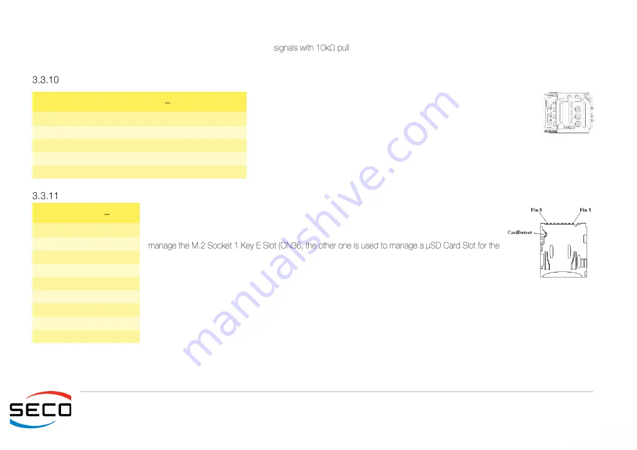
The socket is type MOLEX. p/n 78800-0001or equivalent, with the pinout shown
in the table on the left. Signal are described in the above paragraph.
microSD Slot
The i.MX8 Family of SoCs embeds three Ultra Secured Digital Host controller (uSDHC), able to support
SD / SDIO / MMC Cards.
One of them is used for the implementation of the optional onboard eMMC drive, another is used to
use of standard microSD cards, which can be used as Mass Storage and/or Boot Devices.
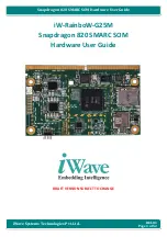
The connector is a microSD connector, push-push type, H=2mm, p/n TFWF1.
SDIO_CLK: SD Clock Line (output).
SDIO_CMD: Command/Response bidirectional line.
SDIO_DAT[0÷3]: SD Card data bus. SDIO_DAT0 signal is used for all communication modes. SDIO_DAT[1÷3] signals are required
for 4-bit communication mode.
microSIM Card Slot CN34
Pin Signal
Pin Signal
1
UIM_PWR
5
GND
2
UIM_RST#
6
---
3
UIM_CLK
7
UIM_DATA
4
---
8
---
μ
SD Card Slot U43
Pin Signal
1
SDIO_DAT2
2
SDIO_DAT3
3
SDIO_CMD
4
+3.3V_RUN
5
SDIO_CLK
6
GND
7
SDIO_DAT0
8
SDIO_DAT1


