


S
hort programming manual is recommended for professional installers who are experienced in
the
installation
of
intruder alarm
systems and have already read the S
ECOLINK
wiring manual.
The wiring manual must be read b
efore the installation to avoid
accidents
with high voltage and temperatur
e.
SAFETY WARNINGS
The device must be connected to AC power supply with Protective Earthing. Cable color and purpose
:
Phase or Live line (L) - black or
brown cable, Neutral line (N) - blue cable, Protective Earth line (PE) - green cable with a vertical yellow stripe. Only double isolated cables
2
with cross-sectional area of no less than 0,75 mm shall be used for 230V power supply.
Additional automatic two-pole circuit breaker should be installed in AC electric power circuit in order to prevent over-current and short
circuits. The circuit breaker should be placed close to the system's housing and should be easily reached. Full shutdown could be done by
turning off the 230V AC main power supply with automatic two-pole circuit breaker and by disconnecting the battery. Before performing
any installation work or maintenance ALWAYS disconnect the device from the power supply.
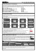
DEFAULT TEMPLATE
STARTING THE SYSTEM WITH A SINGLE KEYPAD
The system is shipped from the factory with specific default values (further default template) suitable for a typical installation. If the default
template is suitable for your installation, then programming can be simplified. If template is not suitable for your
installation
, then you can
easily customize th
is
default template with the software MASCAD. Download MASCAD at www.secolink.eu prior to installation:
On keypad's LCD screen:
Short programming manual - basic information
Intruder alarm system
System with
KM24, KM24A
, KM24G keypads
Entering
Service
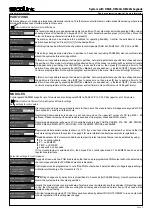
USB cable
KM24x
MASC
USB
Computer
Page
1
Registering
From
KM24
to
CP
Leaving
Service
Note:
the default template can be
different
for different countries. Check
a
sticker
on the
keypad for
a country prefix or pre-installed template code. Example: KM
24G_EN.
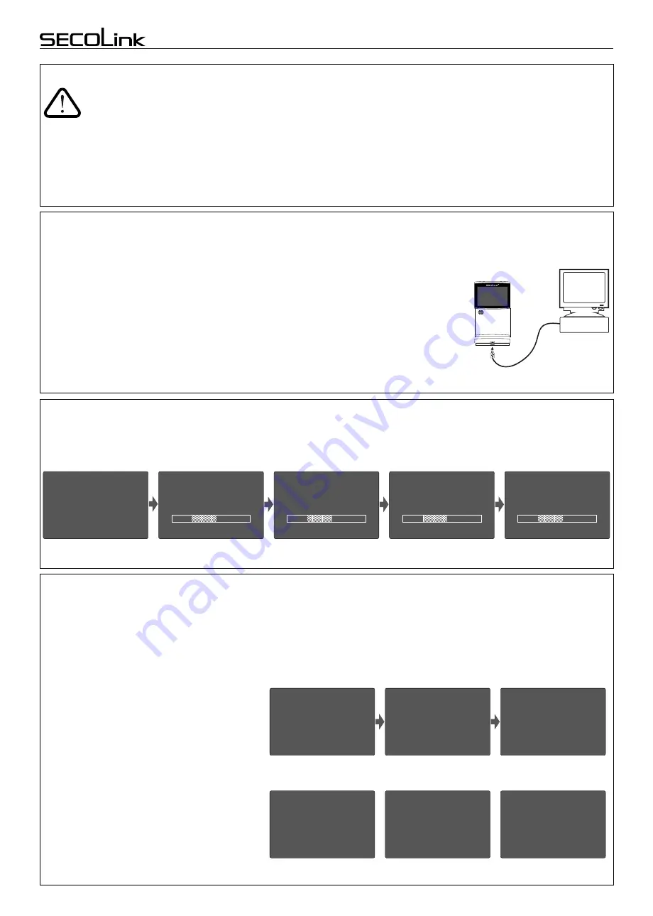
1.Connect the keypad to your computer using a USB cable (keypad should not be connected to
system data bus).
2. Download default template from the keypad to software MASCAD (use the tab
Project data
sending/receiving
).
3.Once you customize the predefined template, you can use it to program an individual system or
thousands of systems.
4. DO NOT FORGET to upload the customized template (further project) back to the keypad (use
the tab
Project data sending/receiving
).
Fig. 1 USB connection
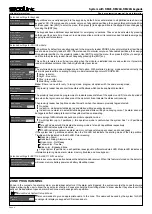
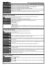
Upon power-up of the system, the keypad will display a phrase
First Start Press [ENT].
It mean
s
that the
keypad
is ready to
run an
automati
c
module registration procedure and later send the default template (or customized project) to the control panel and all
successfully registered system modules.
Processing..
Press
the
[ENT] key.
Template is being sent
to the system.
Registration of modules is
in progress.
Entering Service.
Leaving Service.
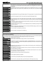
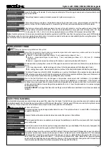
STARTING THE SYSTEM WITH
MULTIPLE
KEYPADS
No Control Address 00
phrase will display upon power-up of the system with multiple keypads.
It means that the keypad ha
s
the same
address in the system as the other keypads or modules.
Press
the
[
Ü
]
key
on a keypad which will become
the
primary keypad.
The p
rimary
keypad should b
ecome the
one which has a customized project
OR it could be any keypad if the
default template is not customized
.
When
the
[
Ü
]
key
is pressed the keypad will emit a short audible signal
and
a
phrase
First Start Press [ENT]
will appear on
the
screen
.
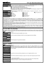
Simply press
[ENT]
i
f the
primary
keypad contains a
customized project
with precise
module addressing
. If the
primary
keypad contains
just a
default
template
, then
use
keys
[1], [2], [3], [4], [5] to manually
assign
the address
to
each keypad.
When all addresses of
the
keypads
are
assigned
, return to the primary keypad and press the
[ENT]
key.
All keypads will be registered according to their addresses, which were
First Start
Press [ENT]
Press
the
[
Ü
] key.
Enter the address
Primary keypad
Used. Choose another.
Processing ...
Assigned address 02.
No Control
Address 00
No Control
Address 00
No Control
Address 0
2
Processing ...
Selecting the primary keypad :
Manually assigning addresses to other keypads:
First Start
Press [ENT]
No Control
Address 0
3
Used
For a small system with a few keypads, it is
recommended to choose
addresses of keypads
in
0
1 -
0
4 range, and for
a
large
system in
0
1 -
0
4 and 10
- 15 range
s
.
This is done in order to not disturb
the
default addresses of other modules with the
addresses of the keypads.
given manually.
Note:
the keypad will remain
unregistered if you
will forget
to assign the address.
Page 1


