


Short programming manual - basic information
Intruder alarm system
System with
KM24, KM24A
, KM24G keypads
Page 11
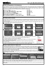
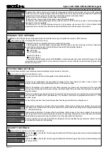
Security Settings
This setting allows to enable or to disable access to the special user menu, where installer with his PIN can
restore 1st user’s PIN to default and the 1st user with his PIN can restore all enabled user PINs to default.
PIN resetting
Disabled
5
Security Settings
Duress code
Disabled
6
This feature is intended for situations where the user is forced to disarm or arm the system under a threat. This
setting enables or disables this feature. Duress code is individual for every system user. Duress code = X1, X2,
X3, X4 when X4 = X4 + 1 (X1, X2, X3, X4 are digits). Example: user PIN is 123
4
, duress code will be 123
5
.
Note:
if certain system
user's A
duress code matches with another system
user's B
PIN code, then the system will use
user's B
PIN instead
of the duress code of
user A
to complete the control action. It is recommended to test duress code availability before using the system. The
event of duress code use will be generated in the event log.
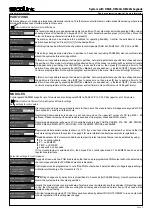
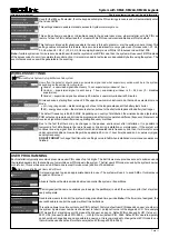
Security Settings
Security Settings
Bypass with PIN
Sys. summary PIN req.
Yes
Yes
3
4
Used for
the
[B] key. If selected, then the keypad will skip the PIN entering procedure and will automatically enter
the 1st user's PIN.
This settings allows to enable or disable access to
System summary
menu.
Service Mode
}
System Setup
}
Wireless Subsystem
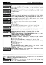
WIRELESS SETTINGS
1
Wireless
Subsystem
Security grade
How often the detector should send a supervision signal and what supervisory window will be in the system
depends upon the setting
Security grade
.
Grade 1
– supervision signal is sent every 1 hour, supervisory window is 1 hour.
Custom
– supervision signal is sent every 1 hour, supervisory window is 0 - 24 hour (0 - disables
supervision).
Grade 2
– supervision signal is sent every 20 minutes, supervisory window is 20 minutes.
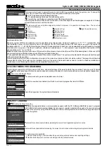
Wireless d
, starting from version
support
evices
2.000
new communication mode, that can be selected in menu
Mode
:
LR
– long range mode – distance is bigger, but due to the longer data packet the battery last shorter.
ES
– energy save mode – the distance is shorter, but due to the shorter data packet the battery last longer.
Grade 1
Wireless
Subsystem
3
Frequency
868,30 MHz
Wireless
Subsystem
2
Mode
LR (Long Range)
The default frequency is 868,30 MHz.
D
epending on country of distribution the wireless devices (detectors,
PGM outputs and remote control) can be programmed at factory to operate on different frequency.
Receiver can
receive a signal from transmitter when operating frequency matches.
Wireless
Subsystem
4
Attenuation
0 dB
Due to the fact that there may be changes in the passive environment after installation, it is possible to
temporarily
for 3dB
attenuate
the radio frequency link during installation or maintenance.
If the system will
continue receiving signal from the detector with an attenuated radio frequency link, then it will work for sure
under normal conditions.
New setting will be applied in 20 min or 1 hour time (depends on supervisory signal
sending frequency).
DO NOT FORGET
to change the
Attenuation
setting's value to
0dB
when installation or maintenance works are
finished.
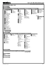
Each installation typically accommodates unique user PIN codes of up to 4 digits. The
Edit Users
menu provides access to submenus and
their related parameters that enable you to maintain
u
ser PIN codes in the system. The first user
’s
PIN code is used by the system’s owner
or chief user. This user has access to all the menus (except
Service mode
) and it can't be disabled.
Main menu
}
Settings
}
Users
}
Edit Users
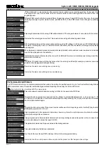
USER PROGRAMMING
1
U01 User 01
Name
User 01
It is recommended to give an appropriate name to a user. The system will use it to send SMS or for display on
keypad's LCD screen.
U01 User 01
Assigned partitions
[ENT]
3
The
Assigned partitions
menu enables you to assign the partition(s) in which the user (except for the 1st system
user) will operate.
This option allows to restore current user PIN to default. Factory default user PIN depends on user's number in
the system. System user number is shown next to letter
U
on top-left corner of the keypad's LCD. For example
U01 means the 1st system user, U02 means the 2nd user, and so on. Default PIN code used by U01 (1st user ) -
0001, U02 (2nd user) default PIN - 0002, ..., U63 (63th user) default PIN - 0063. Default PIN code is temporary
and should be changed as soon as possible to a new one. It is recommended to change the old PIN code to one
that will not be used as default for other users (default PIN range 0000 to 0063).
U01 User 01
Reset PIN to default
Yes
5
U01 User 01
Timers
[ENT]
4
Used to allow users to control the system during predefined time periods.
Note:
if the timer is not assigned, the
user will be able to control the system without time limitations.
U01 User 01
Status
Enabled
2
All users that have the status mode
Enabled
can control
the
system or its partitions.


