background image

13

S

N

O

I

T

C

E

N

N

O

C

R

E

B

M

U

N

N

I

P

S

U

L

P

A

S

8

2

®

P

M

O

C

A

R

T

N

E

L

A

N

I

M

R

E

T

R

O

C

P

R

E

T

N

I

R

P

M

E

D

O

M

M

E

D

O

M

N

O

I

T

P

I

R

C

S

E

D

L

A

N

G

I

S

L

A

N

I

M

R

E

T

K

C

O

L

B

S

5

2

-

B

D

)

E

L

A

M

E

F

(

#

N

I

P

S

9

-

B

D

)

E

L

A

M

E

F

(

#

N

I

P

P

5

2

-

B

D

)

E

L

A

M

(

#

N

I

P

P

5

2

-

B

D

)

E

L

A

M

(

#

N

I

P

P

9

-

B

D

)

E

L

A

M

(

#

N

I

P

D

N

U

O

R

G

L

A

N

G

I

S

1

7

&

1

5

7

&

1

7

5

)

D

X

R

(

A

T

A

D

E

V

I

E

C

E

R

*

2

2

3

*

C

/

N

3

2

)

S

T

C

(

D

N

E

S

O

T

R

A

E

L

C

3

4

7

0

2

8

1

)

S

T

R

(

D

N

E

S

O

T

T

S

E

U

Q

E

R

*

4

5

8

8

&

6

4

7

)

D

X

T

(

A

T

A

D

T

I

M

S

N

A

R

T

5

3

2

3

2

3

D

N

U

O

R

G

H

T

R

A

E

0

1

C

/

N

C

/

N

C

/

N

1

.

4

L

A

N

I

M

R

E

T

O

T

2

L

A

N

I

M

R

E

T

T

C

E

N

N

O

C

,

E

D

O

M

R

E

T

N

I

R

P

D

E

R

I

W

-

D

R

A

H

R

O

F

*

.

L

A

N

G

I

S

"

Y

S

U

B

/

Y

D

A

E

R

"

R

E

T

N

I

R

P

R

O

0

2

N

I

P

*

*

Summary of Contents for ENTRACOMP 28SA Plus

Page 1: ...ENTRACOMP ENTRACOMP ENTRACOMP ENTRACOMP ENTRACOMP 28SA Plus Plus Plus Plus Plus User Installation Manual...

Page 2: ...COPYRIGHT 2002 SOUNDCRAFTINC PRINTED IN U S A...

Page 3: ...INGS 6 GENERAL WIRING INSTRUCTIONS 6 COMMUNICATIONS WIRING FOR SINGLE READER SYSTEMS 9 REMOTE READER CONNECTION 12 CABLE PIN OUTS AND CONNECTION 13 PHYSICAL INSTALLATION SURFACE MOUNT READER 16 PHYSIC...

Page 4: ...IN TERMINAL MODE 43 USING A PRINTER 44 APPENDIX A WIRING SYSTEM CONFIGURATION CONNECTING MULTIPLE 28SA PLUS UNITS A 1 APPENDIX B MODEMS CONNECTING VIA MODEM B 1 APPENDIX C LAN CONNECTION CONNECTING TO...

Page 5: ...stored at one time The ENTRACOMP 28SA Plus hasthreeinputs Eachinputmaybeprogrammed by the user to function as a Door Monitor Tamper Monitor Remote Open Remote Inactive Bell Arming Circuit or User Def...

Page 6: ...ed or when the reset button is pushed see Figure 1 the LED will flash red and green alternately While the LED is flashing place either a Programming Card or an Access Card with the proper facility cod...

Page 7: ...rogram deck cannot be located or when other devices such as bar code scanners transmitter type gate openers or proximity readers are connected to the remote reader input particularly if they are 26 bi...

Page 8: ...NAL CARDS FOR YOUR SYSTEM When you wish to add to an existing set of cards always order additional cards with the same facility code as your existing cards and with sequential Card ID numbering starti...

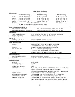
Page 9: ...duplex 1 start bit 8 data bits 1 stop bit no parity RS 485 Requires SK NM485 module at 19 2KBaud Remote Reader 31 bit or 26 bit Wiegand type input 12 VDC 150 mA supplied to remote reader Modem Requir...

Page 10: ...ust be attached to the green screw on the mounting plate WARNING DO NOT APPLY POWERTO UNIT UNTIL ALL CONNECTIONS ARE MADE AND CHECKED GENERAL WIRING INSTRUCTIONS For ease of installation and servicing...

Page 11: ...7 FIGURE 2...

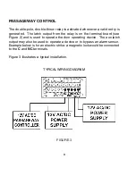
Page 12: ...he terminal board see Figure 2 and is used to operate the door operating device The aux latch output may also be used to operate a device or to bypass an alarm sensor Example below is for an electric...

Page 13: ...ballasts large motors compressors elevators etc Whenever communications cable runs enter or exit a building lightning transient suppressors are strongly recommended at both ends of those cables Parkin...

Page 14: ...ble for connection to the 28SA Plus For example to configure a US Robotics Sportster 14 4 28 8 33 6 or 56 kBaud modem you would type in the following string of characters note that 0 zero AT R1 D0 S0...

Page 15: ...ring for a DB 9S female connector Figure 5 shows wiring for a DB 25S female connector Your PC may have either type of connector on its serial communications ports COM 1 2 3 or 4 REMOTE READER CONNECTI...

Page 16: ...28SA Plus A popular remote reader choice is the Secura Key RK WL long range proximity reader The RK WL reads proximity cards up to three 3 feet away Many drive up applications need the convenience of...

Page 17: ...M N I P P 5 2 B D E L A M N I P P 9 B D E L A M N I P D N U O R G L A N G I S 1 7 1 5 7 1 7 5 D X R A T A D E V I E C E R 2 2 3 C N 3 2 S T C D N E S O T R A E L C 3 4 7 0 2 8 1 S T R D N E S O T T S...

Page 18: ...14 FIGURE 5 FIGURE 6 FIGURE 7 FIGURE 8...

Page 19: ...15 FIGURE 9 FIGURE 10...

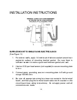
Page 20: ...nt to make a good seal between gasket and wall 2 Use two 6 32 pan head screws not supplied to secure mounting plate to box 3 Connect green grounding screw on mounting plate to Earth ground using a 16A...

Page 21: ...ur of six holes provided 3 Connect green grounding screw on mounting plate to Earth ground using a 16AWG wire 4 Be sure all appropriate wiring has been connected to the terminal board and then plug th...

Page 22: ...ket on the circuit board see wiring instructions Do not apply power until all connections are made 6 Place ENTRACOMP 28SA Plus housing against mounting plate top edge first centering housing on retain...

Page 23: ...19 FIGURE 11 FIGURE 12...

Page 24: ...FIGURE 13 FIGURE 14 20...

Page 25: ...nstallation silicone sealant is recommended between the mounting plate and the wall 5 Connect green grounding screw on mounting plate to Earth ground using a 16AWG wire Also connect green ground wire...

Page 26: ...four holes for appropriate fasteners 8 32 fasteners are recommended 5 Fasten mounting plate to 5S box using the four 8 32 flat head screws provided When running wires to the 5S box don t use the cente...

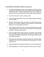
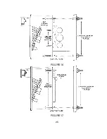
Page 27: ...HOUT 5S BOX See Figure 17 1 Use the wall cutout template provided Locate template on the wall Transfer appropriate cutout corner locations to the wall with a pointed instrument 2 Draw lines from point...

Page 28: ...and then plug the terminal board cable into the socket on the circuit board see wiring instructions Do not apply power until all connections are made 8 Place reader and faceplate assembly against the...

Page 29: ...25 FIGURE 16 FIGURE 17...

Page 30: ...screw 4 Be sure all appropriate wiring has been connected to the terminal board and then plug the terminal board cable into the socket on the circuit board see wiring instructions Do not apply power...

Page 31: ...ing bracket Push housing in against wall Secure housing to mounting bracket in door opening using two 6 32 x 3 8 screws provided Secure housing to bracket at bottom using one 6 32 x 1 4 security screw...

Page 32: ...r mounting bracket Push housing in against wall Secure housing to mounting bracket in door opening using two 6 32 x 3 8 screws provided Secure housing to bracket at bottom using one 6 32 x 1 4 securit...

Page 33: ...29 FIGURE 18 FIGURE 19...

Page 34: ...30 FIGURE 20 FIGURE 21...

Page 35: ...5000 All Cards Time Zone 0 void No Limited Use Settings Latch timer 1 Second APB Timer 0 Minutes off Baud Rate 38 400 Reader ID none Password 12345 Date Undetermined Time Undetermined Time Zones APB...

Page 36: ...Zone Off For All Time Segments Holidays None Set Daylight Savings Correction Automatic Inputs 1 Door Monitor 2 Disabled 3 Disabled Anti Passback Parameters Primary Reader In Out None Daily APB Forgive...

Page 37: ...two kinds of cards used with the ENTRACOMP 28SA PLUS Access Cards and Program Cards Access cards are used by individuals to gain access to the passageway Program cards are used to tell the ENTRACOMP...

Page 38: ...t this point the LED indicator will show an amber color When you remove the Program Card from the TOUCH CARD reader plate the LED indicator will flash the amber color awaiting the next Program Card As...

Page 39: ...1 place the sequence of Program Cards representing the Access Card number on the TOUCH CARD reader plate followed by the VALID card Example Program card number 16 into Time Zone 1 1 6 VALID PROGRAM A...

Page 40: ...d on the reader plate again Next place the sequence of cards representing the Time Zone on the reader plate Place the THRU card on the reader plate again Finally place the VALID card on the reader pla...

Page 41: ...llowed by the ACTIVE INACTIVE card Place unit in Door Unlock mode ACTIVE INACTIVE ToreturntheENTRACOMP 28SA PLUStonormaloperation placethe ACTIVE INACTIVE card on the TOUCH CARD reader plate Return to...

Page 42: ...the sequence of Program Cards representing the number of seconds followed by the SET TIMER card Example Set latch timer to 15 seconds 1 5 SET TIMER PRINTER MODE A serial printer may be connected to t...

Page 43: ...ce the THRU card on the TOUCH CARD reader plate twice in succession Print from Transaction Buffer Once you instruct the unit to print events from the transaction buffer it will begin printing in rever...

Page 44: ...k limits the reuse of a card in a single reader After the card is used it is placed in a temporary VOID status for a number of minutes During the anti passback time that card cannot gain access at tha...

Page 45: ...ction NOTE Anti passback Forgive has no effect on cards that are assigned to a Time Zone with Timed Anti passback To forgive real anti passback for all cards place the THRU card on the TOUCHCARD reade...

Page 46: ...Example Set the date to 9 28 01 9 2 8 0 1 SET TIMER To set the time place the sequence of cards on the TOUCHCARD reader plate that represent the hour 0 24 followed by the THRU card Next place the seq...

Page 47: ...orks with a single reader or a network of readers connected together via RS 485 The multiple location dial up version SK NET MLD allows modem communication TCP IP and unlimited remote locations Direct...

Page 48: ...terminal Be sure to follow the instructions carefully There are two ways to place the ENTRACOMP 28SA PLUS into the printer mode hard wiring or using the Program Deck For Program Deck instructions see...

Page 49: ...p center Figure A2 The module has a 3 wire pigtail which should be connected to the network cable as shown in Figure A1 Up to 128 28SA Plus Units can be connected on the reader network Total combined...

Page 50: ...arking applications where a PC or laptop computer with WINDOWS 95 is unavailable A Serial Printer can be connected to the RS 232 port of any reader to provide real time transaction printing for the en...

Page 51: ...Figure A2 SK NM485 Module Installation A 3...

Page 52: ...recommended in networks with very long wire runs Total system cable length 4 000 ft SERIAL CABLE RS 232 PC or printer to 28SA Plus 6 Conductor Shielded 18 24 AWG Recommended cable Eastman 725 5720 SJ...

Page 53: ...ignal Ground is recommended in networks with very long wire runs Total system cable length 4 000 ft 1 SERIALCABLE RS 232 PC or printer to 28SA Plus 5 Conductor Shielded 18 24 AWG Recommended cable Eas...

Page 54: ...reader without the use of a computer and without setting DIP switches Note that the setup string stored in the 28SA Plus and SK ACP is only used for modems at remote locations If you are using a SK MD...

Page 55: ...r SK ACP The modem is now set to auto answer and dumb mode You can now connect to reader from the PC location Verify that the TR and CD lights are lit on on the modem display NOTE The default baud rat...

Page 56: ...address in your DHCP server 1 Connect a PC to the SK LAN with a serial cable Do not power up the SK LAN yet 2 Run Hyper Terminal Start Programs Accessories Communication HyperTerminal 3 Select the app...

Page 57: ...t cable Connect the included power supply to 110VAC DONOT Plug the Ethernet cable into a telephone jack Substitute another power supply Mount the unit in a wet location or a location where temperature...

Page 58: ...Exit You are now ready to configure your system using SK NET MLD software See Section 2 2 1 4 d for instructions NOTES 1 Always close SK NET before closing WINDOWS to avoid LAN communications failure...

Page 59: ...C 4 LOCATION CONNECTED TO LAN SK LAN PC RUNNING SK NETTM SK ACP GATEWAY PANEL SK ACP SK ACP SK ACP SK ACP 10 BASE T ETHERNET...

Page 60: ...quickly to divert large voltage spikes to ground and away from sensitive components Secura Key SA Series Access Control Units are equipped with surge protection on all inputs and outputs PC s Printer...

Page 61: ...and avoid any bends in the wire Self grounding Surge Protectors Do not use surge protectors unless they are equipped with a separate ground wire or ground screw Self grounding Surge Protectors use the...

Page 62: ...ods The model numbers specified below are the minimum protection needed Some areas may require additional protection If lightning damage persists consult these manufacturers DiversifiedTechnologies Di...

Page 63: ...e clamping level 15VRMS 5 wire DDUAL 5W DTV G 7V With Screw Terminals one side with DB 25 other side pin 2 3 4 7 8 Telephone Line Surge Protectors w screw terminals ground wire clamping level 130VRMS...

Page 64: ...tion expenses THE WARRANTY SET FORTH ABOVE IS EXCLUSIVE AND NO OTHERWARRANTY WHETHERWRITTEN OR ORAL IS EXPRESSED OR IMPLIED SECURA KEY SPECIFICALLY DISCLAIMS ANY IMPLIED WARRANTIES OR MERCHANTABILITY...

Page 65: ...off and on the user is encouraged to try to correct the interference by one or more or the following measures Reorient or relocate the receiving antenna Increase the separation between the equipment...

Page 66: ...20447 Nordhoff Street Chatsworth CA 91311 Phone 818 882 0020 Fax 818 882 7052 TOLL FREE 800 891 0020 Web site www securakey com E mail mail securakey com...

Reviews: