18
tight, stopping when reader cover is at top (12 O’Clock). A small tack weld
is strongly suggested to keep the housing from rotating on post.
2.
Apply 1/8 inch bead of silicone sealant around rear perimeter surface
of mounting bracket gasket.
3.
Press plate against adapter and secure with four 10-32 x 5/16 pan
head screws (provided).
4.
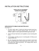
Connect green grounding screw on mounting plate to Earth ground
using a 16AWG wire.
5.
Be sure all appropriate wiring has been connected to the terminal
board, and then plug the terminal board cable into the socket on the
circuit board (see wiring instructions). Do not apply power until all
connections are made.
6.
Place
ENTRACOMP
®
28SA-Plus
housing against mounting plate, top
edge first, centering housing on retaining tabs. Secure housing to
plate at bottom using one 6-32 x 3/8 security screw provided or
equivalent.
7.
Lock cam lock.
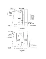
SURFACE MOUNT TO FLANGE (See Figure 14)
1.
Position flange mount adapter (optional) against post flange (not
supplied). Locate and mark four (untapped) holes. Then drill and tap
four 10-32 holes in post flange.
2.
Apply silicone bead around perimeter of post flange. Place flange
mount adapter against post flange and secure with four 10-32 x 1/2 flat
head countersunk screws provided.
3.
Follow instructions 2 - 7 for post mount adapter.
Summary of Contents for ENTRACOMP 28SA Plus
Page 2: ...COPYRIGHT 2002 SOUNDCRAFTINC PRINTED IN U S A...
Page 11: ...7 FIGURE 2...
Page 18: ...14 FIGURE 5 FIGURE 6 FIGURE 7 FIGURE 8...
Page 19: ...15 FIGURE 9 FIGURE 10...
Page 23: ...19 FIGURE 11 FIGURE 12...
Page 24: ...FIGURE 13 FIGURE 14 20...
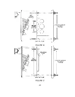
Page 29: ...25 FIGURE 16 FIGURE 17...
Page 33: ...29 FIGURE 18 FIGURE 19...
Page 34: ...30 FIGURE 20 FIGURE 21...

