21
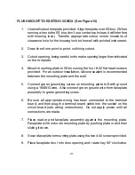
FLUSH MOUNT TO EXISTING 5S BOX (See Figure 15)
1.
Use wall cutout template provided. Align template over 5S box. (When
running wires to the 5S box, don’t use center top hole as it will interfere
with housing lock.) Transfer appropriate cutout corner locations of
clearance hole for the housing lock to the wall with pointed instrument.
2.
Draw lines from point to point, outlining cutout.
3.
Cut out opening, being careful not to make opening larger than indicated
on the template.
4.
Mount mounting plate to 5S box using the four 8-32 flat head screws
provided. For an outdoor installation, silicone sealant is recommended
between the mounting plate and the wall.
5.
Connect green grounding screw on mounting plate to Earth ground
using a 16AWG wire. Also connect green ground wire from faceplate
assembly to green grounding screw.
6.
Be sure all appropriate wiring has been connected to the terminal
board, and then plug the terminal board cable into the socket on the
circuit board (see wiring instructions). Do not apply power until all
connections are made.
7.
Place reader and faceplate assembly against the mounting plate.
Faceplate will hook onto mounting plate by pushing plate in and then
sliding it down.
8.
Secure faceplate to mounting plate using the two 4-40 screws provided.
9.
Place faceplate door into door opening and rotate key 90° clockwise.
Summary of Contents for ENTRACOMP 28SA Plus
Page 2: ...COPYRIGHT 2002 SOUNDCRAFTINC PRINTED IN U S A...
Page 11: ...7 FIGURE 2...
Page 18: ...14 FIGURE 5 FIGURE 6 FIGURE 7 FIGURE 8...
Page 19: ...15 FIGURE 9 FIGURE 10...
Page 23: ...19 FIGURE 11 FIGURE 12...
Page 24: ...FIGURE 13 FIGURE 14 20...
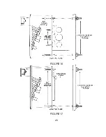
Page 29: ...25 FIGURE 16 FIGURE 17...
Page 33: ...29 FIGURE 18 FIGURE 19...
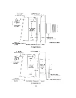
Page 34: ...30 FIGURE 20 FIGURE 21...


