SK-ACPe
InStAllAtIon & oPerAtIng MAnuAl
6
OUTPUTS
Each door controlled by the SK-ACPE has two double pole, double throw relays associated with it. The “latch
relays” are located on “J1” and “J2”, terminals 1-6. The “auxiliary relays” are located on “J3” and “J4”. One
pole of the latch relay is typically used to open or close a circuit to unlock a door or activate a gate operator.
The other pole of the latch relay operates simultaneously and may be used to shunt an alarm contact, start
a video recorder, etc. The auxiliary relay may operate according to a variety of user-defined conditions.
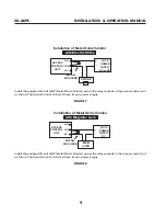
These must be programmed using SK-NET™ software (see SK-NET™ manual). NOTE: Two MOVs (metal-
oxide varistors) are provided with each SK-ACPE. These must be installed between the “Common” and either
the “Normally Open” or the “Normally Closed” terminals where power to the electric lock or strike is being
switched (See Figures 7 and 8). For testing and troubleshooting purposes, an LED indicator is located on the
circuit board adjacent to each relay. The LED lights when the relay is activated.
COMMUNICATIONS JUMPER
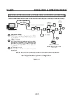
The jumper on pins 2 and 3 of Jumper connector JP1 must be installed to enable RS-232 communications
at Jack J11 and J7. If the SK-WLSE-MOD Wireless network module is installed at J12, this jumper must be
moved to pins 1 and 2 of JP1 to enable RS-232 communications with the wireless module.
LED INDICATORS
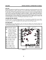
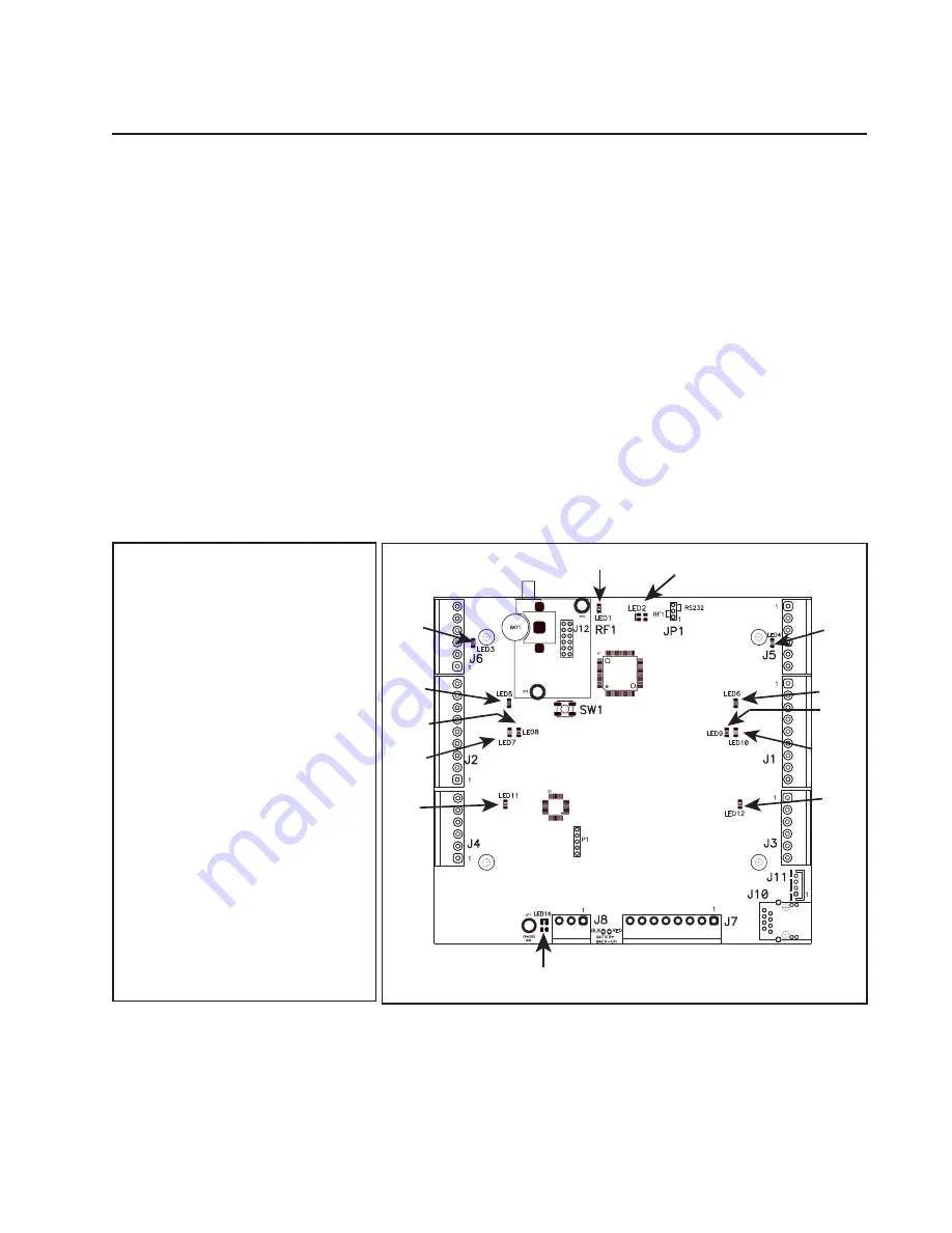
The SK-ACPE features 12 LED indicators, which will assist the installer when connecting, testing and
troubleshooting the readers, inputs and outputs, power and communications wiring. These indicators and
their functions are described in Figure 4.
RS-485
HOST
COMMS
AUX
RELAY1
ACTIVE
AUX
RELAY 2
ACTIVE
INPUT 1-2
ACTIVE
INPUT 1-1
ACTIVE
INPUT 2-1
ACTIVE
INPUT 2-2
ACTIVE
LATCH
RELAY 1
ACTIVE
LATCH
RELAY 2
ACTIVE
READER 1
SHORTED
READER 2
SHORTED
CPU & POWER STATUS*
**WIRELESS COMMS
BLUE BLINK - SEARCHING
SOLID BLUE - CONNNECTED
WIRELESS
ADAPTER COMMS**
*CPU & POWER STATUS
GREEN BLINK - ALL OK
AMBER BLINK - AC POWER FAIL
RED BLINK - BATTERY FAIL
RESET
BUTTON
LED Locations & Legend
LED 1
: WIRELESS ADAPTER COMMS
BLUE BLINK - SEARCHING
SOLID BLUE - CONNECTED
LED 2
: CPU & POWER STATUS
GREEN BLINK - STATUS OK
AMBER BLINK - AC POWER FAIL
RED BLINK - BATTERY FAIL
LED 3
: READER 2 POWER SHORTED
LED 4
: READER 1 POWER SHORTED
LED5
: LATCH RELAY 2 ACTIVE
LED 6
: LATCH RELAY 1 ACTIVE
LED 7
: INPUT 2-2 ACTIVE
LED 8
: INPUT 2-1 ACTIVE
LED 9
: INPUT 1-1 ACTIVE
LED 10
: INPUT 1-2 ACTIVE
LED 11
: AUX RELAY 2 ACTIVE
LED 12
: AUX RELAY 1 ACTIVE
LED 13
: RS-485 HOST COMMS
figure 4
Summary of Contents for SK-ACPE
Page 1: ...SK ACPE User Installation Manual...
Page 2: ...COPYRIGHT 2013...
Page 4: ......
Page 40: ...www SecuraKeyStore com 800 878 7829 sales securakeystore com...


