background image

SK-ACPe   


            InStAllAtIon  &  oPerAtIng  MAnuAl 

8

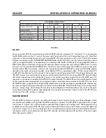
PiN NuMBer CONNeCTiONS

SK-ACP ADVANCeD CONTrOL PANeL

PC Or TerMiNAL

PriNTer

MODeM

SIGNAL DESCRIPTION

J7

DB-25S

(FEMALE) PIN #

DB-9S

(FEMALE) PIN #

DB-25P

(MALE) PIN #

DB-25P

(MALE) PIN#

DB-9

(MALE) PIN#

SIGNAL GROUND

1

1 & 7

5

1 & 7

7

5

RECEIVE DATA (RXD)

2

2

3

N/C

3

2

CLEAR TO SEND (CTS)

3

4

7

20

1

REQUEST TO SEND (RTS)

4

5

8

6 & 8

4

7

TRANSMIT DATA (TXD)

5

3

2

3

2

3

FIGURE 6

RS-232

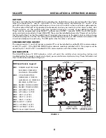
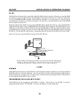
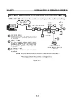
You may connect RS-232 communications to the SK-ACPE either by using plug “J7”, terminals 1-5, or by plugging 
the RS-232E cable into the J11 jack at the lower right hand side of the circuit board (See figure 3).  Note that 
jumper J1 must be installed on pins 2 and 3 to enable RS-232 communications at J7 and J11. RS-232 requires 
at least 5-conductor cable. SUGGESTED CABLE IS Belden 9535. RS-232 is used to connect the COM port of 
a PC to a single SK-ACPE, or as a gateway to a network of SK-ACPEs. (COM ports are typically DB9 male or 
DB25 male jacks on the back of a personal computer.) Newer computers may not have COM ports, in which 
case, you must purchase the SK-USB USB-to-serial converter, which plugs into a USB port on your computer 
and provides a DB-9 connector, which can be connected to the SK-ACPE-LE by using an SK-PLUG9 pigtail, 
extending the cable as long as needed, using Belden 9535 or equivalent cable.  When connecting a PC 
via RS-232 the distance from the panel to the computer should not exceed 100’. (For longer distances, see 
“RS-485” below.) A serial printer may also be connected to the RS-232 port of any SK-ACPE. This will allow 
all system transactions to be printed as they occur. (A printer may be connected to one SK-ACPE even if a 
computer is connected to another SK-ACPE in the same network. The SK-ACPE must be configured for Serial 
Printer operation-See Appendix D.) An external modem might also be connected to the RS-232 port of an 
SK-ACPE for dial-up applications using SK-NET-MLD software. While any Hayes compatible 56K modem may 
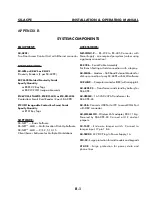
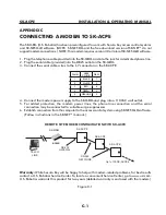
be used, we highly recommend that you use the Secura Key SK-MDM. The SK-ACPE contains the configuration 
data, or “setup string” which allows this modem to be configured in the field without the use of a computer 
and without setting DIP switches. (See Appendix C for modem instructions.) Figure 5 shows the RS-232 pin 
connections for a PC, printer, or modem.

TAMPER SWITCH

The SK-ACPE includes an input for an enclosure Tamper Switch, and it also has an onboard beeper, which 
can provide an audible warning if the SK-ACPE enclosure is opened.  The SK-ACPE is provided with a jumper 
wire across J7, inputs 1 & 6, which should be removed if the tamper switch will be used.  The Tamper Switch is 
available as an accessory, SK-TS-CP, which can be fastened to the enclosure with three screws (included) and 
wired to J7, inputs 1 & 6.  To stop the beeper from sounding during maintenance by authorized technicians, 
the tamper switch can be held down for about 20 seconds, and the beeping will stop (this will be reset again 
after the panel is closed.)

Summary of Contents for SK-ACPE

Page 1: ...SK ACPE User Installation Manual...

Page 2: ...COPYRIGHT 2013...

Page 3: ...ing the SK ACPE with SK NET 3 FACTORY SETTINGS 11 4 READERS AND CARDS 12 Using Secura Key Readers and Cards Using Non Secura Key Readers and Cards Ordering Additional Cards Setting Facility Codes APPE...

Page 4: ......

Page 5: ...able by the user to activate under one of several possible alarm or special conditions SK ACPE will control access for up to 65 535 individuals in 15 weekly time schedules Time Zones independently for...

Page 6: ...ty code will be unchanged In some cases it may be necessary for the unit to recognize more than one facility code Typical instances are when it is necessary to read cards that work in two independent...

Page 7: ...ther than 500 feet 2 Using the unit as a template mark on the mounting surface the location of the four mounting holes 3 Install appropriate mounting hardware anchors retainers etc to the mounting sur...

Page 8: ...6 NO COM NC NO COM NC 6 5 4 3 2 1 1 2 3 4 5 6 NC COM NO NC COM NO 9 8 7 6 5 4 3 2 1 IN 2 COM IN 1 NO COM NC NO COM NC NC COM NO NC COM NO IN 1 COM IN 2 1 2 3 4 5 6 7 8 9 J12 JP1 RJ 45 ETHERNET OPTION...

Page 9: ...igure 3 SUGGESTED CABLE IS Alpha 1296C The SK ACPE will provide up to 400mA to power each reader If the readers you use require more current an external power supply must be used INPUTS Each reader ma...

Page 10: ...able RS 232 communications at Jack J11 and J7 If the SK WLSE MOD Wireless network module is installed at J12 this jumper must be moved to pins 1 and 2 of JP1 to enable RS 232 communications with the w...

Page 11: ...1 1 DOOR MONITOR L A T C H XFMR or POWER SUPPLY ELECTRIC STRIKE or MAG LOCK CABLE TYPES 3 COMMUNICATIONS TO MODEM PC SERIAL PRINTER INPUT 1 2 2 REMOTE DOOR OPEN SWITCH 1 2 3 4 TO RS 485 NETWORK 4 POW...

Page 12: ...uter should not exceed 100 For longer distances see RS 485 below A serial printer may also be connected to the RS 232 port of any SK ACPE This will allow all system transactions to be printed as they...

Page 13: ...oss the relay contacts in the access control unit as shown The Access Control Unit must have its own power supply FIGURE 7 MAG LOCK ACCESS CONTROL UNIT LOCK POWER SUPPLY DC _ N O COM N C INSTALL MOV H...

Page 14: ...re along the RS 485 bus The total RS 485 cable distance including the distance between all SK ACPEs may be up to 4000 Figure 9 shows how each SK ACPE is connected to the RS 485 bus Line A 2 Line B 1 S...

Page 15: ...ermined Time Zones APB Timed Hard Date Restrictions None 0 Always Void 1 Always Valid no restriction 2 Mon Fri 8am 5 30pm 3 Mon Fri 6am 6pm 4 Sat Sun 24 hours 5 Sat Sun 6am 6pm 6 Always Valid Timed An...

Page 16: ...em The SK ACPE cannot distinguish between cards which have different Facility Codes and the same ID Number For example if you have a card with Facility Code A1 and ID Number 15 and you have a card wit...

Page 17: ...isted pairs PC or serial printer Total cable length 100 feet NOTE Same wire to be used for connection from SK ACPE to reader Total cable length 500 feet SK USB may be required if your PC does not have...

Page 18: ...EM ACTIVITY 1 2 SK ACPE Note When using the RS 232 to RS 485 converter you cannot use the stubbed star fanout or T configuration All network connections from SK ACPE to the next SK ACPE must be in par...

Page 19: ...Suggested cable 6 Conductor Shielded with no twisted pairs PC or serial printer Total cable length 100 feet NOTE Same wire to be used for connection from SK ACPE to reader Total cable length 500 feet...

Page 20: ...ORIES NET CONV P RS 232 to RS 485 Converter with Power Supply one required per system unless using a gateway connection RS 232E Serial Cable Assembly For Bench Testing or field connection with a lapto...

Page 21: ...shielded cable with a signal ground Wiegand Input 2 Programmable up to 40 bits 14 VDC 400 mA supplied to each reader Modem Requires Hayes compatible 1 2 to 38 4k baud Printer Serial Printer or Parall...

Page 22: ...3 RED 8 4 GREEN 4 5 ORANGE 2 4 Connect the modem power supply to the SK MDM and plug into a 110VAC wall outlet 5 For added protection the modem power lines the phone line connection and the serial con...

Page 23: ...figure your system using SK NET MLD software see SK NET Manual for instructions NOTES 1 Always close SK NET before closing WINDOWS to avoid LAN communications failures 2 The manufacturer s instruction...

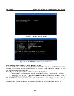
Page 24: ...Select Edit 7 Select Test The SK ACPE Log On Screen displays Fig D 1 8 Type in the Default Password 12345 and press Enter The Device Configuration Screen Fig D 2 will display Ignore any IP addresses...

Page 25: ...terminal program such as SK NET Terminal or HyperTerminal To configure an SK ACPE for the serial transaction printer function 1 Follow Steps 1 7 in the previous section to display the SK ACPE Login Sc...

Page 26: ...con then click OK 6 The Location Information Screen will redisplay but it is not necessary for this setup pro cedure click Cancel then Yes to Confirm Cancel and OK 7 The next screen titled Connect To...

Page 27: ...ransaction screen click on the Filter icon b Click on Defaults Click OK 2 Are you logged in to the Location a From the Explorer screen open the All Readers folder to display reader icon s Are there Gr...

Page 28: ...e working right click on All Readers l Select Backup Select All Readers 1 4 Reader does not read LED is Flashing Red or Green A slowly flashing Red LED indicates that the reader is in the Inactive mod...

Page 29: ...Failure a In the Explorer screen look for a red arrow next to the Location icon This indicates you are connected to the Location b Click on the next to All Readers If the reader shows a green check ma...

Page 30: ...ion box and re check the box next to Gateway RS 232 1 7 NET CONV Converter Connection If you cannot connect and you are connected using the NET CONV converter test voltages as follows 1 Measure input...

Page 31: ...for the replacement This will simplify the following steps used in this procedure Note DO NOT delete any readers from the Explorer screen After completing the replacement of the board you need to sta...

Page 32: ...urge suppression properly grounded off board devices will provide the best protection Where to Install Surge Protection On the AC line voltage input to the PC A UPS with surge protection is recommende...

Page 33: ...or ground screw Self grounding Surge Protectors use the connector shell or Pin 1 as a ground path however the shell and Pin 1 are not always grounded AC Power Surge Protectors AC Power Surge Protector...

Page 34: ...ound wire to a dependable earth ground using a heavy gauge cable 12 or 14 AWG recommended Keep the wire run to the grounding location as short as possible Wiegand output Card Readers and Keypads Conne...

Page 35: ...3 J1 J8 J7 J11 J5 DTK CR CONNECTING THE DTK XR DATA LINE PROTECTION The DTK XR is a multi line surge suppressor that can protect an SK ACPE control panel or other access control unit from damaging pow...

Page 36: ...R DIAGRAM 24VDC EARTH GROUND TELCO 24V 12V 6V TO NEXT PANEL TO PHONE CO PHONE JACK DTK XR 5 4 3 2 1 12 VDC GND 12VDC RS 485A RS R85B RS 232 3 2 1 GND A B WIEGAND IN 8 7 6 5 4 3 2 1 AC AC I O TXD RTS C...

Page 37: ...panel Connect to the LAN via RJ 45 connector J10 at the lower right hand corner of the board A separate module is not required Multiple Ethernet connections in one system require SK NET MLD IP Address...

Page 38: ...he on board surge suppressors to discharge to ground you must connect this terminal to Earth Ground using the supplied ground lug and 10 AWG wire see Figure 3 12 The panel now includes battery monitor...

Page 39: ...mful interference to radio or television reception which can be determined by turning the equipment off and on the use is encouraged to try to correct the interference by one or more or the following...

Page 40: ...www SecuraKeyStore com 800 878 7829 sales securakeystore com...

Reviews: