SK-ACPe
InStAllAtIon & oPerAtIng MAnuAl
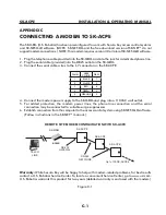
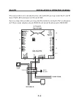
If the access control unit is connected to other units via RS-485 you may connect the “A” and “B”
lines of the RS-485 twisted pair to 6V IN and 6V OUT.
If you are using a dial-up modem, you may protect the modem by running the “Tip” (usually green)
and “Ring” (usually red) phone lines to TELCO IN and connect the phone jack to TELCO OUT.
DTK-XR
DIAGRAM
24VDC
EARTH
GROUND
TELCO 24V 12V 6V
TO NEXT PANEL
TO PHONE CO.
PHONE
JACK
DTK-XR
5 4 3 2 1
12 VDC GND 12VDC RS-485A RS-R85B
RS-232
3 2 1
GND A B
WIEGAND
IN
8 7 6 5 4 3 2 1
AC - AC+ I/O TXD RTS CTS RXD GND
SK-ACPE
6
5
4
3
2
1
RED LED
GREEN LED
14 VDC
SIG GND
DATA 1
DATA 0
9
8
7
6
5
4
3
2
1
IN 2
COM
IN 1
NO
COM
NC
NO
COM
NC
DATA 0
DATA 1
SIG GND
14 VDC
GREEN LED
RED LED
1
2
3
4
5
6
7
8
9
1
2
3
4
5
6
NC
COM
NO
NC
COM
NO
IN 1
COM
IN 2
NO
COM
NC
NO
COM
NC
6
5
4
3
2
1
1
2
3
4
5
6
NC
COM
NO
NC
COM
NO
RJ 45
ETHERNET
RESET
BUTTON
J9
J4
J2
J6
J8
J7
J11
J1
J5
J3
F-5
Summary of Contents for SK-ACPE
Page 1: ...SK ACPE User Installation Manual...
Page 2: ...COPYRIGHT 2013...
Page 4: ......
Page 40: ...www SecuraKeyStore com 800 878 7829 sales securakeystore com...

