SK-ACPe
InStAllAtIon & oPerAtIng MAnuAl
8.
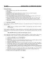
The Reset Button has been moved
– it is next to connector J2.
9.
AC Power is now recommended, due to a redesigned power supply.
A 16.5VAC
40VA transformer such as SK-XFRMR can be used to power the board. 24VDC power
is also recommended, using a DC supply such as SK-DCPWR.
10.
Gas discharge tube surge protectors are now included on the RS-485 bus
(J8)
which interconnects multiple panels, and can be used to connect back to the host PC.
These devices will greatly improve surge protection of the panel, but external surge
protectors are still highly recommended in lightning-prone areas (see Appendix F4, F5).
11.
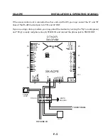
A Chassis Ground Terminal has been added to the PCBA
(left of J8). To allow the
on-board surge suppressors to discharge to ground, you must connect this terminal
to Earth Ground, using the supplied ground lug and 10 AWG wire (see Figure 3).
12.
The panel now includes battery monitoring circuitry
which can report low battery
or AC failure conditions to SK-NET (Version 5.1 is required). These conditions are also
indicated at LED 2.
13.
On-board memory has been increased
, allowing up to 10,000 stored transactions
to be buffered instead of 4800, and allowing up to 65,535 cardholders to be limited
use cards instead of 4000 (SK-NET Version 5.1 is required).
14.
The panel now includes an enclosure tamper input
(J7, pins 1&6) which can be
connected to optional enclosure tamper switch SK-TS. (SK-NET Version 5.1 is required.)
15.
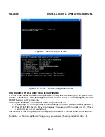
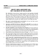
The Serial Transaction Printer function
must now be configured using a Terminal
Program. (See Appendix D).
16
. The Power Reset function
has been enhanced (See Appendix E, section 1.8).
G-2
Summary of Contents for SK-ACPE
Page 1: ...SK ACPE User Installation Manual...
Page 2: ...COPYRIGHT 2013...
Page 4: ......
Page 40: ...www SecuraKeyStore com 800 878 7829 sales securakeystore com...


