SK-ACPe
InStAllAtIon & oPerAtIng MAnuAl
5
POWER & BATTERIES
The SK-ACPE unit must be connected to a source of low voltage power. The SK-ACPE should NOT be connected
to the same power supply that is providing power to an electric lock or strike. To power the SK-ACPE, you
must use a power supply, which is properly rated for the panel, plus any connected equipment:
SK-ACPE with RK-WM / RK-WS readers
24VDC, 500 mA or 16.5VAC 40VA transformer
SK-ACPE with SK-WLSE-MOD
24VDC, 500 mA or 16.5VAC 40VA transformer
Add RK-WL readers to either of the above
16.5VAC 40VA transformer
The basic configuration can be powered by the SK-ACP-PS, which includes a 24VDC 1A supply and a 4AH
backup battery, or by a 16.5VAC 40VA transformer (SK-XFRMR)
Terminals 7 & 8 on plug “J7” must be connected to 16.5 to 24 volts, AC or DC.
You may also connect the
SK-ACPE to 12 VDC, but in this case you must connect your power supply to the red (+) and black (-)
wire leads on the lower left corner of the panel instead of the “J7” plug. If you use 12 VDC you cannot
install a standby battery in the SK-ACPE.
When 16.5 – 24 volts is used to power the SK-ACPE, you may connect the red and black wires to a 12 volt
standby battery. Polarity (+/-) must be observed. The, 10” X 11” SK-ACPE-LE can accommodate batteries
up to 4.0 Amp-hours
Do not energize the SK-ACPE until all other connections are made.
READERS
SK-ACPE is designed to accept any reader or keypad with a standard Wiegand interface. The reader for door
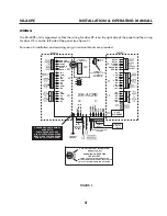
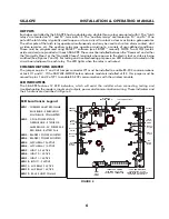
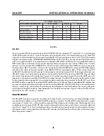
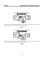
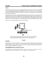
#1 is connected to plug “J5”, the reader for door #2 is connected to plug “J6”. (See figure 3) SUGGESTED
CABLE IS Alpha 1296C. The SK-ACPE will provide up to 400mA to power each reader. If the readers you use
require more current, an external power supply must be used.
INPUTS
Each reader may be associated with up to two auxiliary inputs. Inputs might include remote switches, door contact
sensors, vehicle presence detectors, etc. If you connect inputs to the SK-ACPE you must define those inputs using
SK-NET™ software (see SK-NET™ manual). Note that input 1 (#7) and input 2 (#9) share a common terminal (#8)
on plugs “J1” and “J2”. All inputs are configured as normally open circuits. However, in many cases a “Door Monitor”
input should be a normally closed circuit. To convert any input defined as “Door Monitor” to normally closed, you
must reconfigure the inputs as Normally Closed, using the SK-NET™ software (see SK-NET Manual.) For testing
and troubleshooting purposes, LED indicators are located on the circuit board near the input terminals, just below
the LED Indicator for the Latch Relay (Figure 4). The LED lights when the input is in the alarm (off-normal) state.
CHASSIS GROUND
The SK-ACPE has a chassis ground terminal at the bottom of the PCBA just to the left of J8.
This terminal
must be connected to a good, reliable Earth ground, to enable the on-board gas tube surge
suppressors to work effectively. If this is not done, damage to the controller may result.
A crimp-
type wire lug is supplied with the unit. Secure the lug to the terminal using the provided screw. Crimp the
ground wire to 10AWG stranded, insulated wire, and connect the wire to the closest Earth ground available,
such as a 10-ft buried copper grounding stake, Building Electrical Ground, or a steel cold water pipe, which
must be contiguous, with no PVC or ABS sections.
Summary of Contents for SK-ACPE
Page 1: ...SK ACPE User Installation Manual...
Page 2: ...COPYRIGHT 2013...
Page 4: ......
Page 40: ...www SecuraKeyStore com 800 878 7829 sales securakeystore com...


