background image


Secure Power Ltd


User Manual 

 ………………………………………………………………………………………………………… 

21


Appendix 1 Signals options 

RS232 serial port 

Units are fitted with a standard RS232 serial port, which can be used to: 


Monitor the UPS power status 


Monitor the UPS alarm information 


Monitor the UPS running parameters 


Perform a battery test 

To enable RS232 control: 

1.  Connect the UPS to your computer using the supplied RS232 cable. 

2.  If present, disconnect the USB cable between UPS and your computer. 

Note:

 A USB connection overrides an RS232 connection. 

3.  Load the supplied software onto your computer. 

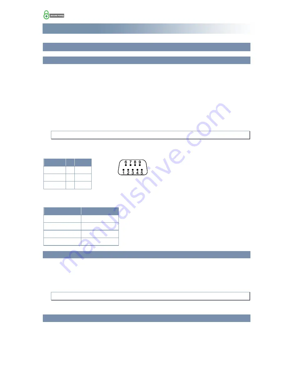
Connections between computer and UPS RS232 ports 

Computer   

UPS 

RDX 2 

  TX 3 

TDX 3 

  RX 2 

GND 5 


GND 5 


RS232 communication data format 

Parameter 

Value 

Baud rate 

2400 bps 

Byte length 

8bit 

End bit 

1bit 

Parity check 

Null 

USB port 

The USB port is internally wired to the RS232 port through a converter and provides the same monitoring 
capabilities as above. 

To enable USB control: 

1.  Connect the UPS to your computer using the supplied USB cable. 

Note:

 This connection will override an RS232 connection. 

2.  Load the supplied software onto your computer. 

SNMP card (advanced monitoring and control) 

If your unit is fitted with the optional SNMP card (located in the Intelligent Slot on the rear panel), connect 
it to your computer with a network cable. 

For instruction on how to operate the SNMP card, refer to the documentation on the supplied CD. 


Figure 5 RS232 serial port pin-outs 

looking at the socket on the UPS 

Summary of Contents for SP201

Page 1: ...td Secure Power Ltd Unit 3 Bessemer Park Bessemer Way Rotherham South Yorkshire S60 1EN Email sales secure power co uk Website www secure power co uk Secure Power Ltd User Manual SP200 Series UPS SP20...

Page 2: ...may not be copied reproduced or disclosed to a third party without written permission Secure Power Ltd reserves the right to make changes in specification without notice or liability All information...

Page 3: ...t 9 Unpacking the UPS 10 Wiring the UPS 10 Operation 11 Working modes 11 On Line mode 11 Bypass mode 11 Battery mode 11 ECO mode 11 Front panel controls and indicators 12 LCD display 13 Before switch...

Page 4: ...serial port 21 USB port 21 SNMP card advanced monitoring and control 21 Relay card advanced monitoring and control 22 Appendix 2 Specifications 24 Electrical 24 Environment 25 Mechanical 25 Appendix...

Page 5: ...requires internal maintenance or battery replacement contact Secure Power Ltd Keep the UPS in a dry well ventilated location away from any area or situation in which there is a risk of fire such as d...

Page 6: ...control systems and telecommunication systems Product range The following table lists the models available in the SP200 series Models with an E suffix are designed for operation with an external batt...

Page 7: ...power factor correction High frequency double conversion and a wide input voltage range ensure continuous output for areas with poor power supply regulation DSP technology for digital control ensures...

Page 8: ...e connectors for input and output respectively If using external batteries you will be supplied with a separate battery box that includes a battery breaker or you may be supplied with a set of battery...

Page 9: ...ure Power Ltd User Manual 9 Rear panel layout Figure 2 and Figure 3 show the rear panel connections for the two sizes of UPS Figure 2 Rear panel layout 1 kVA unit Figure 3 Rear panel layout 2 3 kVA un...

Page 10: ...if fitted Do not use a pozidrive PZ screwdriver To connect the UPS to your system 1 If your system uses an external battery check that the number of 12 V blocks matches the number specified in your or...

Page 11: ...ls a serious fault has occurred within the UPS that must be repaired The UPS is turned off In bypass mode the inverter LED is off and the amber bypass LED is on Battery mode In battery mode the load i...

Page 12: ...e UPS is working in bypass mode The buzzer beeps every 2 minutes When on with the green inverter LED indicates that the UPS working in ECO mode Indicates that the UPS is in battery mode Flashes under...

Page 13: ...e the batteries for at least 8 hours as they may have lost charge during the time between production and installation To switch on the UPS Note If there is no mains and you want to start the UPS and r...

Page 14: ...tching off the UPS Caution All power to the loads will be removed when you follow this procedure To switch off the UPS 1 On the front panel press and hold until a beep is heard after approximately hal...

Page 15: ...stops flashing 4 Press or to display ON which flashes 5 Press for more than 0 5 s but less than 2 s ON stops flashing 6 Press for more than 2 s The green inverter and amber bypass LEDs should be on To...

Page 16: ...for more than 2 s To disable switch to bypass mode Use the procedure above and select OFF instead of ON Output voltage level To change the output voltage Caution Before changing the output voltage tur...

Page 17: ...30 V the default value and 240 V 6 Press for more than 0 5 s but less than 2 s The voltage stops flashing 7 Press for more than 2 s Checking parameters To check the UPS parameters Press or to display...

Page 18: ...cuts off the output or switches to bypass mode and sounds the buzzer The warning LED is lit and the display shows a fault code A list of fault codes is shown on page 27 In this mode you can Mute the...

Page 19: ...aintain the ambient temperature in the range 15 to 25 C Avoid discharge currents of less than 10 of full load current Do not operate the UPS in battery mode continuously for more than the specified au...

Page 20: ...ce the battery Mains normal but UPS has no input UPS input breaker open circuit Reset the input breaker and then make sure there is a mains supply Back up time low Battery not fully charged Recharge t...

Page 21: ...2 GND 5 GND 5 RS232 communication data format Parameter Value Baud rate 2400 bps Byte length 8bit End bit 1bit Parity check Null USB port The USB port is internally wired to the RS232 port through a...

Page 22: ...ion Terminal block connection no DB9 pin no Additional information UPS failure N C 1 1 UPS failure N O 2 1 Bypass active N C 1 3 Bypass active N O 4 6 UPS summary alarm N C 1 5 UPS in battery mode Bat...

Page 23: ...nection table on the previous page and the pin out information below To connect to the 16 way terminal block Note There is limited space between the terminal block and the edge of the mounting slot It...

Page 24: ...Backup time SP201 SP202 SP203 4 mins Suffix E backup time is determined by the size of the external battery Charge current SP201 SP202 SP203 1 A SP201E SP202E SP203E 4 A Output Output type Single pha...

Page 25: ...perating temperature 0 to 40C Storage temperature 25C to 55C Relative humidity 0 to 95 non condensing Altitude 1500 m full power Over 1500m reduce the rated power output by 1 for every 100m increase i...

Page 26: ...ecure Power Ltd User Manual 26 Appendix 3 Optional equipment The following items are available as options for the UPS Extension battery box Dry contact relay card SNMP card Battery MCB box Bypass pane...

Page 27: ...dix 4 Fault codes Fault Fault code Bus Fault 00 19 Inverter Fault 20 39 Over Heat 40 44 Output short circuit 45 49 Overload 50 54 Output Relay Fault 55 59 Input NTC Fault 60 64 Auxiliary Power Fault 6...

Page 28: ...losed Inverter mode Every 4 s Ensure the battery breaker is closed Power up or start Six times Ensure the battery connections are secure 6 Output overload protection Overload warning on line mode Ever...

Reviews: