1
of 12
DEM680E Series Delayed Egress
Magnalock
®
with EcoMag
™
Technology
Installation & Operating Instructions
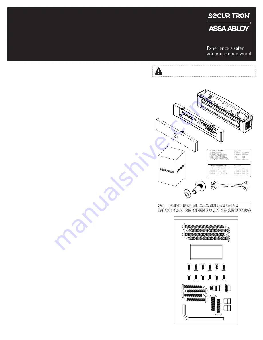
Product Components
A Magnalock & Mounting Bracket
B Strike Housing
C Strike Plate Assembly
D Wall Mounted Key Switch
E Settings Labels
F Sex Bolt & Tapered Washer
G Template Pins
H NFPA Door Label
Installation Hardware Pack Contents
I #14 X 3" Type A Phillips
Pan Head Screw (4)
J Threadlocker Packet
K WOOD DOORS: #6 X
1/2" Phillips Flat Head
Type A Steel Screw (6)
L METAL DOORS: 6-32 X
3/8" Phillips Flat Head
Type F Steel Screw (6)
M #12 X 1-1/2" Type A Phillips
Pan Head Screw (4)
N Rivet Nut Install Tool
O 1/4-20 X 1" Phillips Pan
Head Screw (2)
P 1/4-20 Rivet Nut (2)
Q 3/16" Hex Key
Diagram 1
Product Components
A
C
D
E
F
G
H
I
J
K
L
M
N
O
P
Q
B
Specifications
Dimensions
•
Height: 2.50" [64 mm]
•
Depth: 2.56" [65 mm]
•
Length: 11.50" [292 mm]
Certifications
•
UL 10C Fire Rated, 1 Hour
•
CAN/ULC-S104 Fire Door Conformant
•
UL 294
•
UL Tested Ratings: Endurance:
100,000 cycles
•
ANSI/BHMA A156.23, Grade
2; E18501 Compliant
•
California State Fire Marshal Listed
•
NFPA 101
Electrical
•
Magnalock Minimum Current Draw
(±10%)
95 mA at 12 VDC
65 mA at 24 VDC
•
Magnalock Maximum Current Draw
(±10%)
575 mA at 12 VDC
315 mA at 24 VDC
Static Holding Force
•
1,200 lbs [544kg]
Operating Temperature
•
32˚ to 120˚F [0˚ to 49˚C]
•
Indoor use only
NOTE: Hardware is provided for various installations.
There will be leftover parts depending on the type of installation.
IMPORTANT: UL 294 compliance requires that the locking device be powered by a UL
294 (ALVY) or UL 603 (APHV) listed power supply and shall be installed in accordance
with the following UL and National Standards: NFPA 70 – National Electrical Code.
IMPORTANT
This Magnalock requires calibration upon installation.


