5
of 12
4
of 12
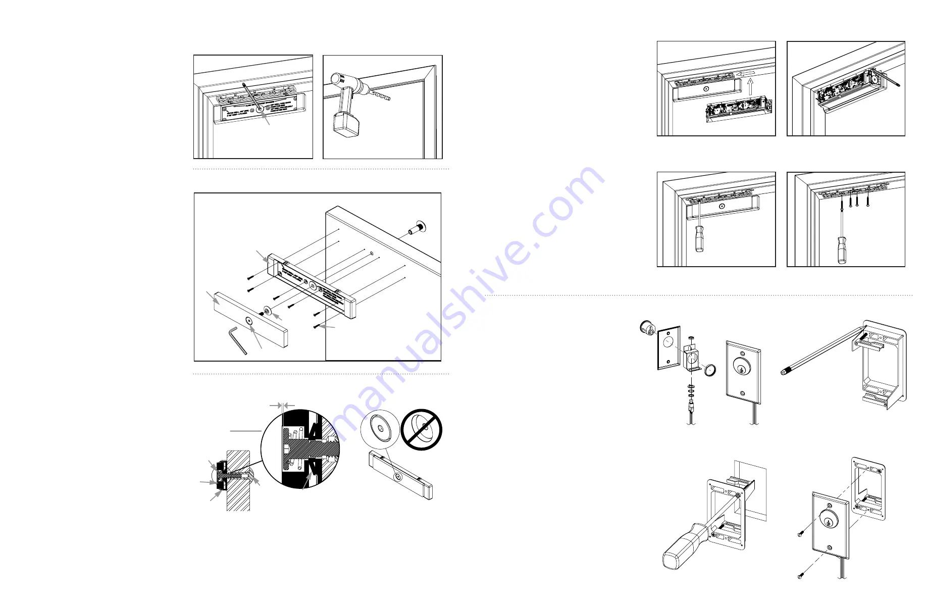
Diagram 11 Marking the
strike housing mounting hole
locations from the inside
Diagram 13 Securing the plate assembly to the door
Diagram 14 Strike assembly
installed – section view
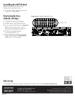
Diagram 16 Mounting the
Magnalock to the bracket
Diagram 18 Tightening
the mounting screws
Diagram 20 Assembling
the key switch plate
Diagram 22 Installing
the mounting device
Diagram 15 Strike assembly
installed – inside door
Diagram 17 Marking the back
edge of the mounting bracket
Diagram 19 Installing the
final mounting screws
Diagram 21 Marking the wall cut-out
Diagram 23 Installing the key switch
Diagram 12 Drilling the sex
bolt hole from the outside
Installing the strike
on the door
1
With the door closed, ALIGN the strike housing
with the template pins as indicated on the
strike housing. Ensure the strike housing is
pushed up snug against the template pins.
2
MARK seven strike housing mounting
hole locations (see
Diagram 11
).
3
REMOVE the strike housing from the door and the
template pins from the lock mounting bracket.
From the INSIDE
4
DRILL a level 3/8" diameter hole for the
sex bolt all the way through the door at
the strike mounting center mark.
5
FOR A HOLLOW METAL DOOR:
DRILL six (6) #36
(0.107") holes through the inside skin of the door for
the strike housing mounting screws.
FOR A WOOD DOOR:
DRILL six (6) #36 (0.107)" x 1/2"
deep holes for the strike housing mounting screws.
From the OUTSIDE
6
FOR A HOLLOW METAL DOOR:
DRILL out the
3/8" diameter sex bolt hole to 1/2" diameter in the
outside skin of the door (see
Diagram 12
).
FOR A WOOD DOOR:
DRILL out the
3/8" diameter sex bolt hole to 1/2"
diameter completely through door.
Secure the strike plate
assembly to the door
7
INSERT the sex bolt into the hole from the
outside of the door (see
Diagram 13
).
8
ATTACH the strike plate housing using six (6) 6-32 x
3/8" Phillips flat-head screws for METAL
–OR–
six (6)
#6 x 1/2" Phillips flat-head screws for WOOD door.
9
CRITICAL STEP:
PLACE the tapered washer on the
strike assembly screw with the smaller diameter
surface of the washer facing against the back
of the strike plate, as shown in
Diagram 14
.
10
APPLY thread-lock compound (included)
to the strike assembly screw.
11
INSERT the strike assembly screw through the
strike housing and door and into the sex bolt.
12
CRITICAL STEP:
TIGHTEN the screw into the sex
bolt using the 3/16" hex wrench. While tightening,
gently tap the head of the sex bolt using a rubber
mallet until the head sits flush with the door.
NOTE:
To provide maximum door movement after
installation, the head of the strike assembly screw should be
approximately 0.025" (about the thickness of a paperclip)
below the surface of the strike as shown in
Diagram 15
.
NOTE:
DEM680E detects door movement through a concealed
‘patent pending’ strike assembly. OVERTIGHTENING the strike
assembly screw will reduce door movement range and may cause
false alarms. DO NOT OVERTIGHTEN the strike assembly screw.
Mounting the
Magnalock and aligning
to the strike plate
1
SLIDE the Magnalock assembly to fully engage
the lock chassis to the mounting bracket. Install
one of the three screws through one of the top
chassis holes and into the mounting bracket to
temporarily secure the Magnalock (see
Diagram 16
).
2
SLIDE the lock forward or backward so
that the entire face makes contact with
the strike plate on the closed door.
3
MARK the back edge of the mounting bracket
at each end and remove the Magnalock
from the bracket (see
Diagram 17
).
4
ENSURE that the mounting bracket
aligns with the marks and TIGHTEN the
mounting screws (see
Diagram 18
).
5
USING THE BRACKET AS A TEMPLATE, DRILL pilot
holes as necessary, then install and tighten the four
(4) final mounting screws (see
Diagram 19
).
FOR HOLLOW METAL DOORS
: DRILL 3/16" holes and
use #12 x 1-1/2" screws.
FOR WOOD DOORS:
DRILL 7/32"
holes and use #14 x 3" screws.
6
RETURN the Magnalock to the bracket and secure
the chassis to the bracket with three (3) screws.
Installing the
wall-mounted switch
1
ASSEMBLE the cylinder and switch to the wall-
mounted key switch plate (see
Diagram 20
).
2
MARK the corners for the mounting device
at the desired locations on the wall and
create a cut-out (see
Diagram 21
).
3
INSERT the mounting device into the cut-
out and fasten it in place with a Phillips
screwdriver (see
Diagram 22
).
4
MAKE the wire connections and install the
key switch plate using a flat-tip screwdriver
and two 6-32 screws (see
Diagram 23
).
Mark all seven (7) holes
Approximate .025"
Only hand tighten
strike assembly
screw
Strike
Assembly
Screw
Tapered Washer
Orientation
Strike
Plate
Sex Bolt
Strike
Housing
Metal Door: 6x 6-32 X 3/8" Self
Tapping Phillips Flat Head Screws
Wood Door: OOv #6 X 1/2" Type
A Phillips Flat Head Screws
STRIKE HOUSING
STRIKE PLATE
STRIKE ASSEMBLY SCREW
3/16" HEX KEY
TAPERED
WASHER
DOOR
SEX BOLT


